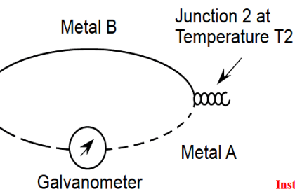
The voltage generated by a thermocouple is a function of the temperature difference between the measurement and reference junctions.
Traditionally the reference junction was held at 0 °C by an ice bath, as shown in Figure.
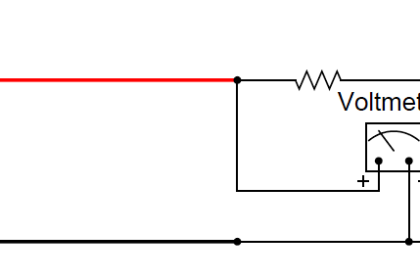
The thermocouple emf is measured with a high impedance voltmeter.

The relationship between thermocouple voltage and temperature is unfortunately not linear, and it is necessary to use thermocouple temperature conversion tables to find temperature from the measured voltage.
An extract from the voltage / temperature table for a type K thermocouple (0 °C reference), is given in Table.
Temperature (°C) versus emf (μV) for type K thermocouple with 0 °C reference.

Table : The Top First Row & Left First Column indicates temperature scales. First Left Column indicates temperature in units 10 deg C and Top First Row indicates temperatures in units 1 deg C. The remaining cells indicates respective thermocouple output voltage in μV units.
For example Temperature is 10 Deg C then from the above table, the equivalent thermocouple output voltage is 397μV. Say now temperature is 12 Deg C then output voltage is 477μV.
Similarly if the temperature is 105 Deg C then from the above table, thermocouple output voltage is 4303μV. The thermocouple tables will change with type of thermocouple. The above shown is for K-type thermocouple.
We could store these look-up table values in a computer/controller and use the table to convert between emf and temperature.
A more viable approach used by manufacturers however, is to approximate the table values using a power series polynomial equations and allow the instrument’s microprocessor or process computer, to calculate temperature from emf or the emf from temperature (inverse polynomial).
The ice bath cold junction is not considered practical anymore. Instead the terminals connecting the thermocouple to the measuring device, are now assumed to play the role of the reference junction or ‘cold junction’, as it is still called today. The reference junction temperature may now be kept, for example, at room temperature, where the junction temperature is measured with an auxiliary temperature sensor, such as a semiconductor/IC type.
According to the law of intermediate temperatures, the thermocouple voltage that corresponds to the cold junction temperature, may be added to the measured thermocouple voltage. The true temperature of the hot junction, with respect to 0 °C, can then be determined from this augmented voltage.
Also Read : Thermocouples Questions and Answers
Example 1 :
Calculate the average sensitivity (μV/°C) of a type K thermocouple in the temperature range 0 °C to 100 °C.
Answer :
From Above Table : the change in emf developed by a type K thermocouple from 0 °C to 100 °C, is 4096 μV.
The average sensitivity is therefore 4096/100 = 40.96 μV/°C.
Example 2 :
The cold junction of a type K thermocouple is kept at 0 °C. Use Above Table to determine the temperature if the measured voltage is
a) 798 μV and b) 2602 μV.
Answer :
From the above Table, we can note the respective temperatures from the given voltage value.
a) 20 °C b) 64 °C
Example 3 :
The relationship between emf and temperature for a certain (imaginary) thermocouple, is described by the relation: v = t2, where v is the generated thermocouple emf in microvolt (μV), and t the temperature difference in °C, between the hot junction and 0 °C. If the thermocouple emf reading is 3000 microvolt and the temperature of the cold junction is 25 °C, calculate the temperature of the hot junction.
Answer :
Emf corresponding to (25 – 0) °C = 252 = 625 μV
Total emf (T – 0) = 3000 + 625 = 3625 μV
According to the law of intermediate temperatures:
Hot junction temperature T = √v = √3625 = 60.21 °C
(T is NOT = √3000 + 25 = 54.77 + 25 = 79.77 °C)
Example 4 :
An unknown temperature is measured with a type K thermocouple. A thermocouple voltage of 2602 μV is measured. If the cold junction temperature is 20 °C, calculate the process temperature, measured by the hot junction side of the thermocouple.
Answer :
From Above Table, the cold junction (20°C) emf is 798 μV. According to the law of intermediate temperatures, the correction voltage of 798 μV should be added to the measured voltage of 2602 μV, to obtain 3400 μV. The corrected voltage represents the thermocouple emf that would be obtained, if the reference junction was kept at 0 °C.
Again from Table, the temperature that corresponds to 3400 μV, is somewhere between 83 °C and 84 °C.
To find the correct temperature, we must use linear extrapolation between these two values.
The difference between 3433 μV (84 °C) and 3391 μV (83 °C) is 42 μV, while 3400 μV is 9 μV more than 3391 μV (83 °C).

Therefore the temperature we are looking for is 83 °C plus (9/42) °C, which is 83.2143 °C.
The way NOT to calculate the hot junction temperature, is to look up the measured voltage (2602 μV) as 64 °C and then to add the cold junction temperature of 20 °C, to obtain 84 °C. This is NOT CORRECT.
Download : Thermocouple Calculator


Nice topic. Very useful
Hi,
I would advise “TC Converter” for the best bi-directional conversion accuracy and cold-junction temperature compensation accuracy. It is a free utility and can be downloaded from http://tdogan.net/#tcc
we can calculate temprature in a thermocouple from given milivolt , as we will take an example .
example – if given voltage is 40mv then find the temprature in that thermocouple.
answer- 2.5 MULTIPLY 40= 100 degree celsius
Thanks