Inst ToolsInst ToolsInst Tools
  • Courses
  • Automation
    • PLC
    • Control System
    • Safety System
    • Communication
    • Fire & Gas System
  • Instrumentation
    • Design
    • Pressure
    • Temperature
    • Flow
    • Level
    • Vibration
    • Analyzer
    • Control Valve
    • Switch
    • Calibration
    • Erection & Commissioning
  • Interview
    • Instrumentation
    • Electrical
    • Electronics
    • Practical
  • Q&A
    • Instrumentation
    • Control System
    • Electrical
    • Electronics
    • Analog Electronics
    • Digital Electronics
    • Power Electronics
    • Microprocessor
  • Request
Search
  • Books
  • Software
  • Projects
  • Process
  • Tools
  • Basics
  • Formula
  • Power Plant
  • Root Cause Analysis
  • Electrical Basics
  • Animation
  • Standards
  • 4-20 mA Course
  • Siemens PLC Course
Reading: Induction Motor Interview Questions & Answers
Share
Font ResizerAa
Inst ToolsInst Tools
Font ResizerAa
  • Courses
  • Design
  • PLC
  • Interview
  • Control System
Search
  • Courses
  • Automation
    • PLC
    • Control System
    • Safety System
    • Communication
    • Fire & Gas System
  • Instrumentation
    • Design
    • Pressure
    • Temperature
    • Flow
    • Level
    • Vibration
    • Analyzer
    • Control Valve
    • Switch
    • Calibration
    • Erection & Commissioning
  • Interview
    • Instrumentation
    • Electrical
    • Electronics
    • Practical
  • Q&A
    • Instrumentation
    • Control System
    • Electrical
    • Electronics
    • Analog Electronics
    • Digital Electronics
    • Power Electronics
    • Microprocessor
  • Request
Follow US
All rights reserved. Reproduction in whole or in part without written permission is prohibited.
Inst Tools > Blog > Electrical Q & A > Induction Motor Interview Questions & Answers

Induction Motor Interview Questions & Answers

Last updated: September 16, 2016 1:24 pm
Editorial Staff
Electrical Q & A
No Comments
Share
5 Min Read
SHARE

[1] How does the Induction motor work? (OR) Why does the Rotor rotate?

  • When the 3 phase stator windings are fed by 3 phase supply, a magnetic flux of constant magnitude which is rotating at synchronous speed is set up.
  • The flux passes through the air-gap and sweeps past the rotor surface  thus it cuts the rotor conductors.
  • Due to the relative speed between the rotating flux and the stationary rotor conductors, an emf is induced in the stationary rotor conductors as per the Faraday’s laws of electromagnetic induction.
  • The frequency of the induced emf is the same as the supply frequency.
  • Its magnitude is proportional to the relative velocity between the flux and the conductors.
  • Its direction will be as per Fleming’s right hand rule.
  • Since the rotor conductors form a closed circuit the rotor current is produced.
  • This current’s direction will oppose the very cause producing it ( as per Len’s law)
  • Here the cause is the relative velocity between the rotating flux of the stator and the stationary rotor conductors.
  • Hence, in order to reduce the relative speed, the rotor begins to rotate in the same direction as that of the rotating magnetic flux and tries to catch up with the rotating flux. Thus the rotor of induction motor starts to rotate.

[2] What is the general working principle of Induction motor?

  • The conversion of electrical power into mechanical power takes place in the rotating part of an electric motor.
  • In DC motors the electrical power is conducted directly to the armature through brushes and commutator.
  • Thus the DC motor can be called as conduction motor. But in case of AC motors, the rotor receives electric power, not by conduction but by induction.
  • This is exactly in the same way as the secondary of two winding transformer receives its power from the primary.
  • That is why such motors are known as induction motors.
  • Thus an induction motor is also known as rotating transformer ( ie, one in which primary winding is stationary and the secondary is free to rotate)
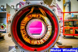
[3] What is the advantage of skewed stator slots in the rotor of Induction motors?


In the induction motor design, the rotor slots are purposely made with a slight skew arrangement. It will not be parallel to the shaft.
This is for the purpose of reducing magnetic locking or reducing magnetic attraction between stator and rotor teeth.
In addition to that this arrangement will help to reduce the magnetic hum and noise.


[4] What is meant by cogging in the Induction motor? How to prevent the cogging?


When the number of teeth in stator and rotor are equal, the stator and rotor teeth have a tendency to align themselves exactly opposite to each other, since this corresponds to minimum reluctance position. In such case the rotor may refuse to accelerate. This phenomenon is called as magnetic locking or cogging.
This problem can be prevented by proper choice of stator and rotor slots and also by skewing the rotor slots by one slot pitch.


[5] What are the various methods of measuring slip?


1. By actual measurement of rotor speed
2. By measurement of rotor frequency
3. Stroboscopic method


[6] What are the various methods of speed control in three phase induction motors?


(i) Control from stator side
1. By changing the supply frequency
2. By changing the number of stator poles
3. By changing the supply voltage
(ii) Control from rotor side
1. By inserting resistance in rotor circuit
2. By various ways of cascade connection
3. By injecting EMFs in the rotor circuit.


[7] What is meant by crawing in the induction motor?


In induction motors, particularly squirrel cage type induction motors, sometimes exhibit a tendency to run stably at speeds as low as one-seventh of their synchronous speed Ns. This phenomenon is known as crawling of an induction motor and the speed is called as crawling speed.
Don't Miss Our Updates
Be the first to get exclusive content straight to your email.
We promise not to spam you. You can unsubscribe at any time.
Invalid email address
You've successfully subscribed !

Continue Reading

High Voltage and Power System Stability Interview Questions
Generator Protection Interview Questions & Answers
Top 100 Power Electronics Questions & Answers
Interview Questions & Answers on Alternators
Protection Relays Interview Questions & Answers
Transformers Questions & Answers Part-2
Share This Article
Facebook Whatsapp Whatsapp LinkedIn Copy Link
Share
Leave a Comment

Leave a Reply Cancel reply

Your email address will not be published. Required fields are marked *

Stay Connected

128.3kFollowersLike
69.1kFollowersFollow
210kSubscribersSubscribe
38kFollowersFollow

Categories

Explore More

Circuit Breaker Interview Questions & Answers
Most Asked Questions on Servo Motor (Answers)
Basic Power Electronics Interview Questions
Electrical Drives Questions & Answers
Power Systems Operation and Control Interview questions
Electrical Machines Short Answers
Three Phase Induction Motor Interview Questions & Answers
Single Phase Induction Motors Questions and Answers

Keep Learning

Induction Motor Protection Interview Questions

Induction Motor Protection Interview Questions Answers

VFD Interview Questions and Answers

VFD Interview Questions and Answers – Electrical Drives

Electric Drives and Traction Objective Questions and Answers

Electric Traction Objective Questions and Answers

Power System Protection and Relays Questions & Answers

Power System Protection and Relays Questions & Answers

Electrical Drives and Controls Interview Questions

Electrical Drives and Controls Interview Questions

DC machines and Induction Machines Viva Questions & Answers

Transformers Questions and Answers

Latest Transformers Questions and Answers

Interview Questions on Transformers

Interview Questions on Transformers

Learn More

Kv-value of a valve is determined by a standardised test

Calculate Flow Coefficient Kv of Solenoid Valve

Burnout Function in Temperature Transmitter

Burnout Function in Temperature Transmitter

DC machines and Induction Machines Viva Questions & Answers

Steps in PLC System Design

Steps in PLC System Design

Derivative Controller Response

Derivative Controller Principle

PID block from the PLC library

How to Configure PID Controller in Various Schneider PLCs?

Why 24 Volts DC Power Supply

Why 24 Volts DC Power Supply is used? – Industrial Automation Systems

Electrical Machines Questions and Answers

Induction Motors Operating Characteristics Questions

Menu

  • About
  • Privacy Policy
  • Copyright

Quick Links

  • Learn PLC
  • Helping Hand
  • Part Time Job

YouTube Subscribe

Follow US
All rights reserved. Reproduction in whole or in part without written permission is prohibited.
Welcome Back!

Sign in to your account

Username or Email Address
Password

Lost your password?