Inst ToolsInst ToolsInst Tools
  • Ask
  • Courses
  • Videos
  • Q & A
    • Interview
      • Instrumentation
      • Electronics
      • Electrical
      • Practical Questions
    • MCQ
      • Instrumentation MCQ
      • Electrical MCQ
      • Electronics MCQ
      • Control Systems MCQ
      • Analog Electronics MCQ
      • Digital Electronics MCQ
      • Power Electronics MCQ
      • Microprocessor MCQ
      • Multiple Choice Questions
  • EE
    • Electronics
      • Electronics Q & A
      • Electronic Basics
      • Electronic Devices & Circuits
      • Electronics Animation
      • Digital Electronics
    • Electrical
      • Electrical Basics
      • Electrical Q & A
      • Power Electronics
      • Electrical Machines
      • Electrical Animation
      • Power Systems
      • Switchgear & Protection
      • Transmission & Distribution
  • Measure
    • Control Valves
    • Calibration
    • Temperature
    • Pressure
    • Flow
    • Level
    • Analyzers
    • Switches
    • Vibration
    • Solenoid Valve
  • Control
    • PLC Tutorials
    • Control Systems
    • Safety Instrumented System (SIS)
    • Communication
    • Fire & Gas System
  • More
    • Design
    • Tools
    • Animation
    • Basics
    • Formulas
    • Standards
    • TextBooks
    • Common
    • Software
    • Excel Tools
    • Erection & Commissioning
    • Process Fundamentals
    • Videos
    • Books
Search
All rights reserved. Reproduction in whole or in part without written permission is prohibited.
Reading: How to test SCR using Multimeter
Share
Notification Show More
Font ResizerAa
Inst ToolsInst Tools
Font ResizerAa
  • Courses
  • PLC Tutorials
  • Control Systems
Search
  • Ask
  • Courses
  • Videos
  • Q & A
    • Interview
    • MCQ
  • EE
    • Electronics
    • Electrical
  • Measure
    • Control Valves
    • Calibration
    • Temperature
    • Pressure
    • Flow
    • Level
    • Analyzers
    • Switches
    • Vibration
    • Solenoid Valve
  • Control
    • PLC Tutorials
    • Control Systems
    • Safety Instrumented System (SIS)
    • Communication
    • Fire & Gas System
  • More
    • Design
    • Tools
    • Animation
    • Basics
    • Formulas
    • Standards
    • TextBooks
    • Common
    • Software
    • Excel Tools
    • Erection & Commissioning
    • Process Fundamentals
    • Videos
    • Books
Follow US
All rights reserved. Reproduction in whole or in part without written permission is prohibited.
Inst Tools > Blog > Power Electronics > How to test SCR using Multimeter

How to test SCR using Multimeter

Last updated: May 18, 2017 9:33 am
Editorial Staff
Power Electronics
No Comments
Share
2 Min Read
SHARE

This post will discuss about testing SCR – Silicon Controlled Rectifier with thte help of Ohmmeter.

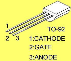
The thyristor pin assignment  diagram of TO-220 package is given for ready reference.

How to test SCR using Multimeter

Identify the terminals of the Ohmmeter:

  • Using a junction diode, we can find out which ohmmeter lead is positive and which is negative.
  • Connect the general purpose PN junction diode to across the positive and negative terminals of the Ohmmeter.
  • The ohmmeter will indicate continuity only when the positive lead is connected to the anode of the diode and the negative lead is connected to the cathode.
  • The SCR can be tested with an ohmmeter based on this concept.

Procedure to Test the SCR with the help of Ohmmeter:

  • To test the SCR, connect the positive output lead of the ohmmeter to the anode and the negative lead to the cathode.
  • The ohmmeter should indicate no continuity.
  • Touch the gate of the SCR to the anode.
  • The ohmmeter should indicate continuity through the SCR.
  • When the gate lead is removed from the anode, conduction may stop or continue depending on whether the ohmmeter is supplying enough current to keep the device above its holding current level.
  • If the ohmmeter indicates continuity through the SCR before the gate is touched to the anode, it indicates that the SCR is shorted.
  • If the ohmmeter will not indicate continuity through the SCR after the gate has been touched to the anode, it indicates that the SCR is open.
Don't Miss Our Updates
Be the first to get exclusive content straight to your email.
We promise not to spam you. You can unsubscribe at any time.
Invalid email address
You've successfully subscribed !
Top 100 Power Electronics Projects for Engineering Students
Thyristor Protection Circuits (SCR) – Types, Principle, Explanation
Turning Off SCR – Commutation
How to Test TRIAC with Multimeter
Power Electronics – Phase Controlled Half Wave Rectifier RL Load
Share This Article
Facebook Whatsapp Whatsapp LinkedIn Copy Link
Share
Leave a Comment

Leave a Reply Cancel reply

Your email address will not be published. Required fields are marked *

Stay Connected

128.3kFollowersLike
69.1kFollowersFollow
208kSubscribersSubscribe
38kFollowersFollow

Categories

Recent Comments

  • Guifty Shimica on Top Non-PLC Certification Courses for Automation Professionals
  • Guifty Shimica on Top Non-PLC Certification Courses for Automation Professionals
  • MIHARITSOA Aina Sitraka on Top Non-PLC Certification Courses for Automation Professionals
  • Vaishnavi on Free Instrumentation Course for Trainee Engineers

Related Articles

Types of Power Electronic Devices

Power Electronic Devices Specification and Classification

SCR Class B Resonant-Pulse Commutation

Thyristor Commutation Techniques – Types, Working Principles

Full-Controlled Rectifier Working Principle

Single-Phase Mid-Point Converter – Bridge Rectifier with Center Tap

R R-C Firing Circuits Disadvantages

R R-C Firing Circuits Disadvantages

Power MOSFET Symbols

Power MOSFET – Symbol, Types, Working, Characteristics, Advantages

IGBT Switching Characteristics

IGBT – Symbol, Construction, Working, Characteristics, Advantages

Thyristor Interview Questions & Answers

Thyristor Interview Questions & Answers

Resistance firing of an SCR in a half-wave circuit

Thyristor Triggering Circuits – Types, Explanation, Waveforms (SCR)

More Articles

PLC Latching circuit Animation

What is Seal-in Circuit ?

Solenoid Valve Design

Solenoid Valve Selection Criteria

Three Phase Induction Motor Interview Questions & Answers

Three Phase Induction Motor Interview Questions & Answers

Simatic Prosave HMI

How to Backup and Restore from Simatic Prosave HMI?

Procedure for the Repair of Control Valve

Basic Steps and Procedure for the Repair of Control Valve

Signal Isolator

What is a Signal Isolator? Principle, Advantages, Disadvantages

PLC Retrofitting Project

What is a PLC Retrofitting Project? – Importance, Procedure

Top 100 Power Electronics Questions & Answers

Top 100 Power Electronics Questions & Answers

Follow US
All rights reserved. Reproduction in whole or in part without written permission is prohibited.
Welcome Back!

Sign in to your account

Username or Email Address
Password

Lost your password?