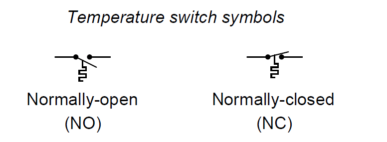
A temperature switch is one detecting the temperature of some substance. Temperature switches often use bimetallic strips as the temperature-sensing element, the motion of which actuates one or more switch contacts.
Temperature Switch Principle
An alternative design uses a metal bulb filled with a fluid that expands with temperature, causing the switch mechanism to actuate based on the pressure this fluid exerts against a diaphragm or bellows. This latter temperature switch design is really a pressure switch, whose pressure is a direct function of process temperature by virtue of the physics of the entrapped fluid inside the sensing bulb.
The “normal” status of a switch is the resting condition of no stimulation. A temperature switch will be in its “normal” status when it senses minimum temperature (i.e. cold, in some cases a condition colder than ambient – check below note). For a temperature switch, “normal” status is any sensed temperature below the trip threshold of the switch.
Note : If the trip setting of a temperature switch is below ambient temperature, then it will be “actuated” at ambient temperature and in its “normal” status only when the temperature falls below that trip point (i.e. colder than ambient).
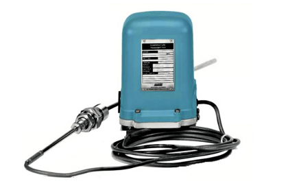
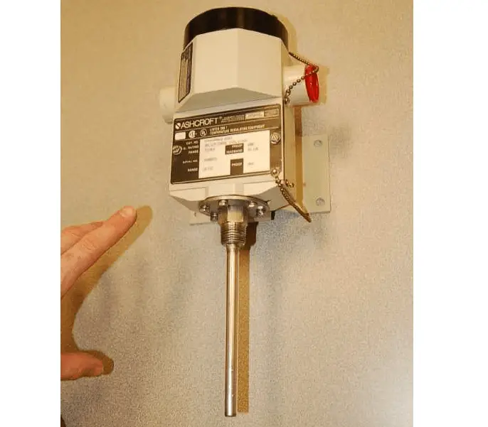
The following photograph shows a temperature-actuated switch manufactured by the Ashcroft corporation:
Like all other process switches, temperature switches exhibit a certain amount of deadband in their switching action.
A temperature switch that trips at 300 oF rising, for example, will not re-set at 300 oF falling. That switch would more likely reset at some lower temperature such as 295 oF.
With mechanical switch designs, some amount of deadband is inevitable due to friction inside the mechanism. However, process switch deadband is actually a useful characteristic as it helps avoid repeated “nuisance” alarms from happening.
To understand this concept, it is helpful to imagine a scenario where the process variable is at or very near the trip point. For our hypothetical temperature switch with a trip point of 300 oF (rising), imagine a situation where the process temperature is precisely 300.0 oF.
Any further rise in temperature will of course trip the switch (sounding an alarm). With no deadband, however, the switch will immediately re-set when the temperature falls back down to 300.0 oF.
This means the switch may possibly “cycle” back and forth between its trip and reset states with just a minute change in process temperature (300.0 oF to 300.1 oF and back again). If the temperature switch is activating an alarm every time it trips, it will create a series of alarm events prompting operators to repeatedly acknowledge the alarm.
This is a nuisance to operations personnel, as it distracts them from addressing what they already realize is a process problem. It is better for the switch to trip at 300.0 oF rising and remain in that tripped state until the temperature falls down to some degree substantially below the trip point.
This way, the operators only receive one alarm event rather than multiple alarm events for each process temperature excursion.
Some mechanical temperature switches come equipped with a separate adjustment for deadband (also called differential ). Setting this deadband adjustment in a mechanical temperature switch requires the technician to repeatedly subject the sensing element to a rising and falling temperature, to check that the switch trips at the proper setting and resets at the proper setting.
This is analogous to cycling the process variable back and forth when adjusting the “zero” and “span” settings of an analog transmitter: checking to see that the transmitter repeatedly outputs a 0% signal at the lower range value (LRV) and a 100% signal at the upper range value (URV).
For discrete temperature-sensing applications demanding high accuracy and repeatability, electronic temperature switch circuits using thermocouples, RTDs, or thermistors may be used instead of a mechanical (bi-metallic or filled bulb) sensing element. The operation and configuration of discrete electronic temperature switches is very similar to that of continuous electronic temperature transmitters.
An example of an electronic temperature switch module is the Moore Industries model SPA (“Site Programmable Alarm”), shown here:
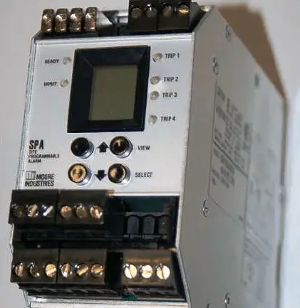
Not only is this particular model capable of directly interpreting both RTD and thermocouple signals, but it will also input 4-20 mA loop current signals as well.
This means you may build a temperature switch system out of a 4-20 mA loop-powered temperature transmitter (located in the field) and an SPA switch module (located in a protected environment such as a control room or electrical enclosure). Many other manufacturers and models of electronic switching units exist, with the Moore Industries SPA being just one example.
With electronic temperature switches, the adjustment of deadband (differential) is both precise and flexible. Unlike mechanical switches where deadband is primarily a function of friction, and therefore liable to change over time as the device wears, electronic switching circuits may be precisely set for any trip and reset points along its measurement range, remaining very stable over time.