Inst ToolsInst ToolsInst Tools
  • Courses
  • Automation
    • PLC
    • Control System
    • Safety System
    • Communication
    • Fire & Gas System
  • Instrumentation
    • Design
    • Pressure
    • Temperature
    • Flow
    • Level
    • Vibration
    • Analyzer
    • Control Valve
    • Switch
    • Calibration
    • Erection & Commissioning
  • Interview
    • Instrumentation
    • Electrical
    • Electronics
    • Practical
  • Q&A
    • Instrumentation
    • Control System
    • Electrical
    • Electronics
    • Analog Electronics
    • Digital Electronics
    • Power Electronics
    • Microprocessor
  • Request
Search
  • Books
  • Software
  • Projects
  • Process
  • Tools
  • Basics
  • Formula
  • Power Plant
  • Root Cause Analysis
  • Electrical Basics
  • Animation
  • Standards
  • 4-20 mA Course
  • Siemens PLC Course
Reading: Thermocouples Sources of Error
Share
Notification Show More
Font ResizerAa
Inst ToolsInst Tools
Font ResizerAa
  • Courses
  • Design
  • PLC
  • Interview
  • Control System
Search
  • Courses
  • Automation
    • PLC
    • Control System
    • Safety System
    • Communication
    • Fire & Gas System
  • Instrumentation
    • Design
    • Pressure
    • Temperature
    • Flow
    • Level
    • Vibration
    • Analyzer
    • Control Valve
    • Switch
    • Calibration
    • Erection & Commissioning
  • Interview
    • Instrumentation
    • Electrical
    • Electronics
    • Practical
  • Q&A
    • Instrumentation
    • Control System
    • Electrical
    • Electronics
    • Analog Electronics
    • Digital Electronics
    • Power Electronics
    • Microprocessor
  • Request
Follow US
All rights reserved. Reproduction in whole or in part without written permission is prohibited.
Inst Tools > Blog > Temperature Measurement > Thermocouples Sources of Error

Thermocouples Sources of Error

Last updated: August 4, 2018 9:55 pm
Editorial Staff
Temperature Measurement
1 Comment
Share
3 Min Read
SHARE

Homogeneity (Wire Uniformity)

With thermocouples the main error lies not with stem conduction but with errors arising from inhomogeneity of the thermocouple wire. Therefore for reliable and consistent results the wires must be homogenous, i.e. the wire must have uniform properties, throughout.

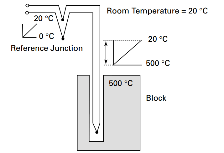
The resultant output e.m.f. from a thermocouple is proportional to the temperature difference between the two junctions. The e.m.f. is generated not at the junction but in the part of the wire that passes through the temperature gradient between the measuring junction and the reference junction. As the e.m.f. is generated in the part of the wire in the temperature gradient then changing the immersion depth will change the position along the wire where the e.m.f. is generated. If the wire properties are different then errors occur.

There is nothing magical about the junction and it is a mistake to think that the e.m.f. is generated at the junction.

Thermocouples Calibration Errors

There is debate relating to the wisdom of calibrating thermocouples. Whilst the best method would be to calibrate thermocouples in situ, this is frequently not possible. As this is a practical guide to calibrating sensors, and thermocouples are calibrated in metal block baths, then the approach recommended here is to carefully consider the homogeneity.

It follows that the leads from the thermocouple should not be run through unnecessary temperature gradients and joins in the wire should be avoided when possible. When joins are made they should not be positioned in a temperature gradient.
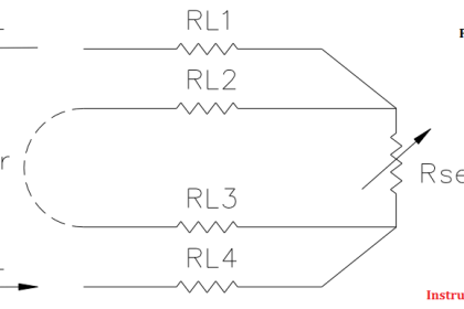
Lead Resistance

This is generally less of a problem with thermocouples than p.r.t.’s, particularly with modern instrumentation. Manufacturers of thermocouple instruments may specify a maximum loop resistance, typically 100 ohms.

Thermal Lag

For thermocouples built into large sheaths or thermowells, this effect needs to be as considered for p.r.t.’s. For thermocouples constructed from fine wires the thermal lag tends not to be significant; indeed such a sensor may be selected for its fast response properties.

Thermal Capacity

As with Thermal Lag this may be an issue for larger assemblies but not for fine wire thermocouples.

Cold Junction Compensation (CJC) Errors

For simple instruments the CJC is built into the device, e.g. a field temperature transmitter. This will typically consist of a internal temperature-sensing device that measures the temperature of the junction of the thermocouple wire and the instrument and an uncertainty of +/- 1ºC, or more, may be expected.

Also Read : RTD Sources of Errors

Don't Miss Our Updates
Be the first to get exclusive content straight to your email.
We promise not to spam you. You can unsubscribe at any time.
Invalid email address
You've successfully subscribed !

Continue Reading

Formula of 2 Wire RTD, 3 Wire RTD & 4 Wire RTD
What is a Probe Thermometer? How to Calibrate and Use it?
What is a Thermocouple ?
Types of Thermowells
Spiral Bimetallic Thermometer Principle
RTD Questions and Answers
Share This Article
Facebook Whatsapp Whatsapp LinkedIn Copy Link
Share
1 Comment
  • T R Raja says:
    January 6, 2020 at 2:10 pm

    we are facing an error in temperature measurement we are taken take two comparing thermocouples and standard thermocouple on calibrating comparing thermocouple say A and B reads 1 to 2 Deg error on reaching 700 Deg the difference is coming around 8 Deg.C this happens tree times will you give solution/Reason for that

    type K type
    outer insulation fiber glass 1 time,
    bare wire with ceramic beads 2 nd time
    ceraamic fiber insulation 3 rd time.

    Reply

Leave a Reply Cancel reply

Your email address will not be published. Required fields are marked *

Stay Connected

128.3kFollowersLike
69.1kFollowersFollow
210kSubscribersSubscribe
38kFollowersFollow

Categories

Explore More

Temperature Error of 2-Wire, 3-Wire & 4-Wire RTD
How to calculate Thermocouple Temperature by measuring the output millivoltage
Thermocouple Calculations
RTD Calculator Software
Calculate Temperature Coefficient of RTD
Thermocouples Law of Intermediate Metals
Temperature Sensor Failure
Temperature Measurement Objective Questions

Keep Learning

Thermocouple Software compensation

Thermocouple Software compensation

Thermocouple Temperature Measurements Errors

Thermocouple Temperature Measurement Errors

Thermowell Installation near Critical Equipment

Thermowell Installation near Critical Equipment

Thermocouple Testing

Thermocouple Cold Junction Compensation

How Does an Infrared Thermometer Work

How Does an Infrared Thermometer Work?

RTD Calibration

RTD Calibration

RTD Construction

Introduction to RTDs

calibrating-and-testing-rtd-sensors

RTD Calibration Procedure

Learn More

Magnetic Flow Meter Corrosion Effects

Magnetic Flow Meter Corrosion Effects

Transmitter Performance and Calibration Frequency

How to Calculate Transmitter Performance and Calibration Frequency?

How to Use the Shift and Rotate Instructions in PLC

How to Use the Shift and Rotate Instructions in PLC?

Pump and Mixer Operations Example PLC Timer-Based Control

Pump and Mixer Operations Example: PLC Timer-Based Control

Temperature Gauges and Elements Specifications

Temperature Gauges and Elements : Detailed Specifications

Non-variable reducing valves

What is Reducing Valve ?

CNC Milling Machine

CNC Milling Machines: What Are They And How Do They Work?

What is an Altitude Valve

What is an Altitude Valve?

Menu

  • About
  • Privacy Policy
  • Copyright

Quick Links

  • Learn PLC
  • Helping Hand
  • Part Time Job

YouTube Subscribe

Follow US
All rights reserved. Reproduction in whole or in part without written permission is prohibited.
Welcome Back!

Sign in to your account

Username or Email Address
Password

Lost your password?