One of the most important accessories for any temperature-sensing element is a pressure-tight sheath known as a thermowell. This may be thought of as a thermally conductive protrusion into a process vessel or pipe allowing a temperature-sensitive instrument to detect process temperature without opening a hole in the vessel or pipe. Thermowells are critically important for installations where the temperature element (RTD, thermocouple, thermometer, etc.) must be replaceable without de-pressurizing the process.
Thermowells may be made out of any material that is thermally conductive, pressure-tight, and not chemically reactive with the process. Most thermowells are formed out of either metal (stainless steel or other alloy) or ceramic materials.
A simple diagram showing a thermowell in use with a temperature gauge is shown here:
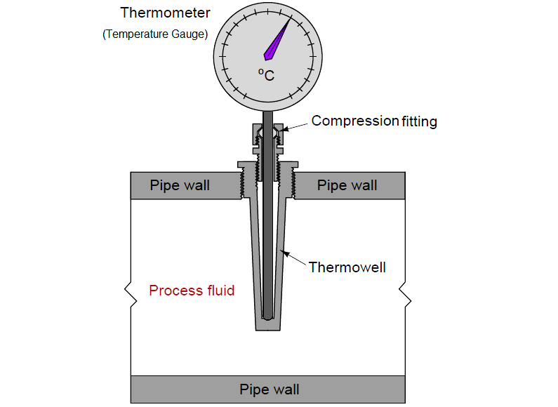
In general, it is better to install a thermowell in a pipe rather than in a vessel because the greater fluid turbulence of flow in a pipe expedites heat transfer by convection as well as helps to clean solid fouling off of the thermowell’s surface.
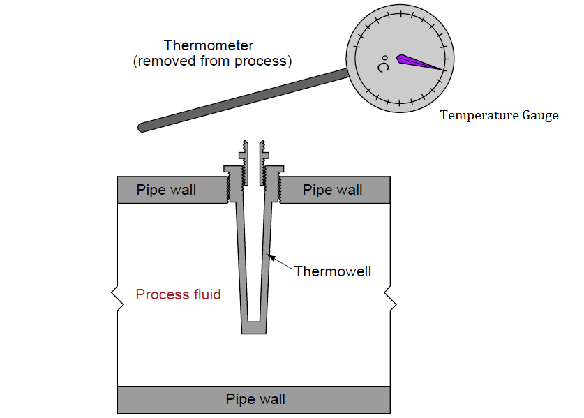
If the temperature gauge is removed for maintenance or replacement, the thermowell maintains pressure integrity of the pipe (no process fluid leaking out, and no air leaking in):
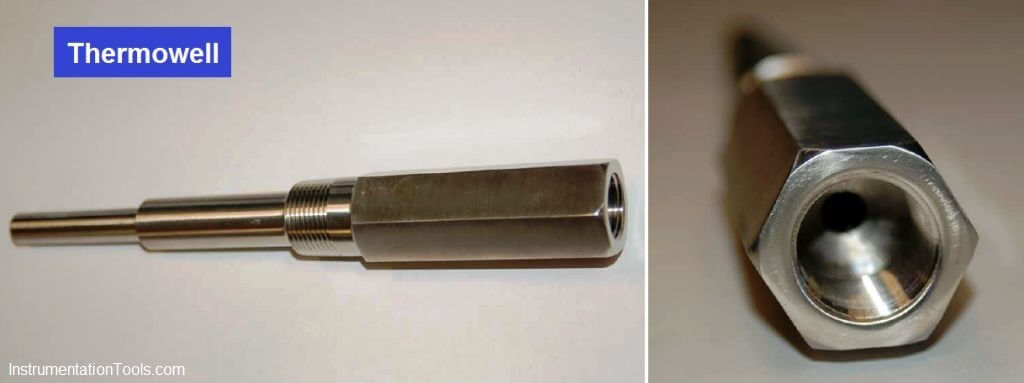
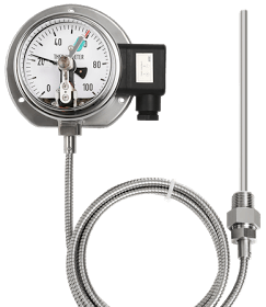
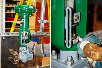
Photographs of a real (stainless steel) thermowell are shown here, the left-hand photo showing the entire length of the thermowell, and the right-hand photo showing the end where the temperature sensing device is inserted:
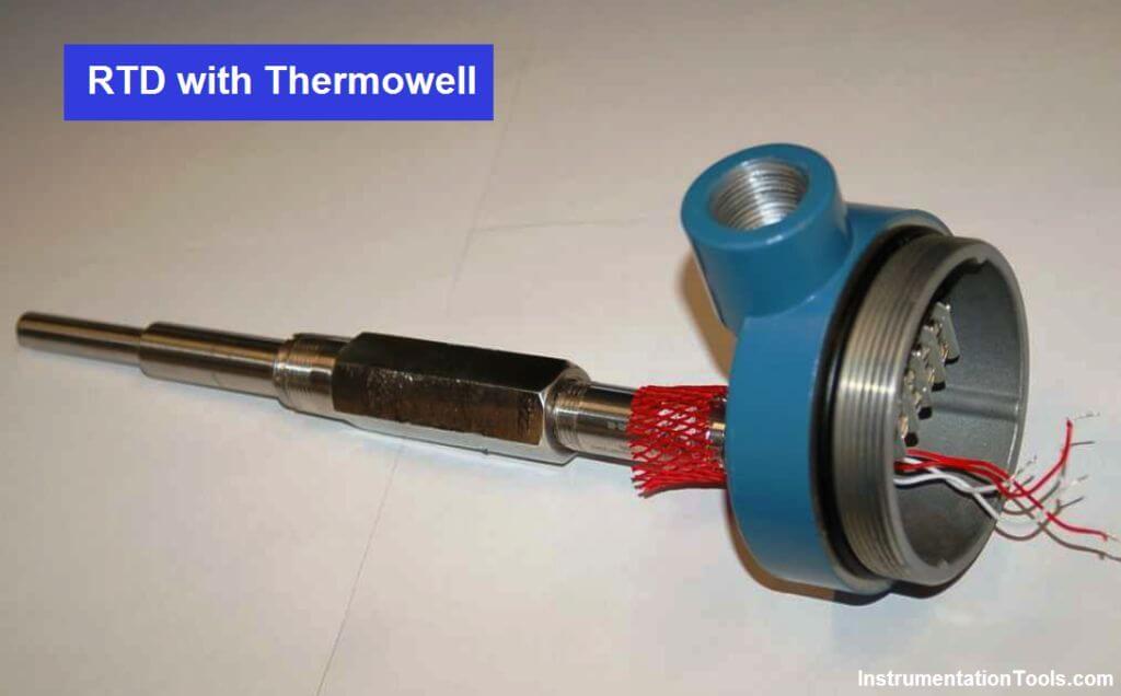
A photo of a complete RTD assembly (connection head, RTD, and thermowell) appears in the next photograph:
As useful as thermowells are, they are not without their caveats. All thermowells, no matter how well they may be installed, increase the first-order time lag of the temperature sensor by virtue of their mass and specific heat value. It should be intuitively obvious that a few pounds of metal will not heat up and cool down as fast as a few ounces’ worth of RTD or thermocouple, and therefore the addition of a thermowell to the sensing element will decrease the responsiveness of any temperature sensing element. What is not so obvious is that such time lags, if severe enough, may compromise the stability of feedback control. A control system receiving a “delayed” temperature measurement will not see the live temperature of the process in real time due to this lag.
A potential problem with thermowells is incorrect installation of the temperature-sensing element. The element must be inserted with full contact at the bottom of the thermowell’s blind hole. If any air gap is allowed to exist between the end of the temperature element and the bottom of the thermowell’s hole, this will add a second time lag to the measurement system (Note). Some thermowells include a spring clip in the bottom of the blind hole to help maintain constant metal-to-metal contact between the sensing element and the thermowell wall.
Note : The air gap acts as a thermal resistance while the mass of the element itself acts as a thermal capacitance. Thus, the inclusion of an air gap forms a thermal “RC time constant” delay network secondary to the thermal delay incurred by the thermowell. This adds another “order” of lag to the system, not just an increase in its thermal time constant. Generally speaking, multiple orders of lag are detrimental to process control because they increase phase shift in a feedback loop and may lead to oscillation.
Process/instrument suitability
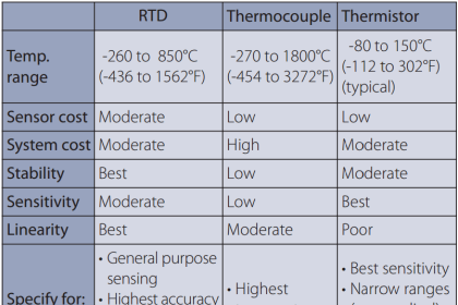
The primary consideration for selecting a proper temperature sensing element for any application is the expected temperature range. Mechanical (bi-metal) and filled-system temperature sensors are limited to relatively low process temperatures, and cannot relay signals very far from the point of measurement.
Thermocouples are by far the most rugged and wide-ranging of the contact-type temperature sensors. Accuracies vary with thermocouple type and installation quality.
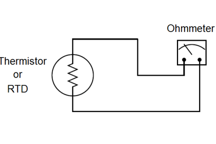
RTDs are more fragile than thermocouples, but they require no reference compensation and are inherently more linear.
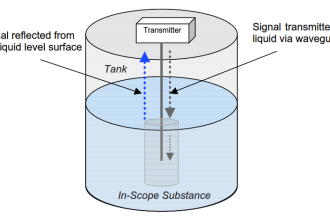
Optical sensors lack the ability to measure temperature of fluids inside vessels unless a transparent window is provided in the vessel for light emissions to reach the sensor. Otherwise, the best an optical sensor can do is report the skin temperature of a vessel. For monitoring surface temperatures of solid objects, especially objects that would be impractical or even dangerous to contact (e.g. electrical insulators on high-voltage power lines), optical sensors are the only appropriate solution.
Chemical reactivity is a concern for contact-type sensors. If the sensing element is held inside a thermowell, that thermowell must be selected for minimum reaction with the process fluid(s). Bare thermocouples are particularly vulnerable to chemical reactions given the nature of most thermocouple metals (iron, nickel, copper, etc.), and must be carefully chosen for the particular process chemistry to avoid reliability problems later.
Credits : Tony R. Kuphaldt – Creative Commons Attribution 4.0 License


So the sheath is inserted into the thermowell? In short what are the advantages of inserting the sensor into the thermowell over inserting the sensor with a stainless steel sheath directly into the process?