Inst ToolsInst ToolsInst Tools
  • Courses
  • Automation
    • PLC
    • Control System
    • Safety System
    • Communication
    • Fire & Gas System
  • Instrumentation
    • Design
    • Pressure
    • Temperature
    • Flow
    • Level
    • Vibration
    • Analyzer
    • Control Valve
    • Switch
    • Calibration
    • Erection & Commissioning
  • Interview
    • Instrumentation
    • Electrical
    • Electronics
    • Practical
  • Q&A
    • Instrumentation
    • Control System
    • Electrical
    • Electronics
    • Analog Electronics
    • Digital Electronics
    • Power Electronics
    • Microprocessor
  • Request
Search
  • Books
  • Software
  • Projects
  • Process
  • Tools
  • Basics
  • Formula
  • Power Plant
  • Root Cause Analysis
  • Electrical Basics
  • Animation
  • Standards
  • 4-20 mA Course
  • Siemens PLC Course
Reading: T-Junction Traffic Control System – PLC Programming
Share
Font ResizerAa
Inst ToolsInst Tools
Font ResizerAa
  • Courses
  • Design
  • PLC
  • Interview
  • Control System
Search
  • Courses
  • Automation
    • PLC
    • Control System
    • Safety System
    • Communication
    • Fire & Gas System
  • Instrumentation
    • Design
    • Pressure
    • Temperature
    • Flow
    • Level
    • Vibration
    • Analyzer
    • Control Valve
    • Switch
    • Calibration
    • Erection & Commissioning
  • Interview
    • Instrumentation
    • Electrical
    • Electronics
    • Practical
  • Q&A
    • Instrumentation
    • Control System
    • Electrical
    • Electronics
    • Analog Electronics
    • Digital Electronics
    • Power Electronics
    • Microprocessor
  • Request
Follow US
All rights reserved. Reproduction in whole or in part without written permission is prohibited.
Inst Tools > Blog > PLC Tutorials > T-Junction Traffic Control System – PLC Programming

T-Junction Traffic Control System – PLC Programming

This article is about a T-junction traffic control system with the help of a PLC ladder logic using a comparator for lights operation.

Last updated: May 2, 2023 10:16 am
K Mugunthan
PLC Tutorials
No Comments
Share
7 Min Read
SHARE

This article is about a T-junction traffic control system with the help of a PLC ladder logic using a comparator for lights operation.

Contents
T-Junction Traffic Control SystemDescription of Inputs and OutputsPLC Programming and its ExplanationConclusion

T-Junction Traffic Control System

The function of the T-junction traffic control system consists of three groups of segments. By the logic of comparator operation, we control the Traffic lights system.
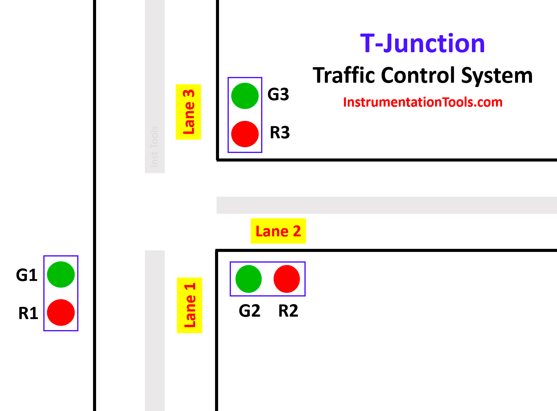
T-Junction Traffic Control System
  • First segment:

In the first segment, lane 1 traffic is allowed and lane 2 and lane 3 are stopped. Here in this segment, the green light (Green 1) of lane 1 glows, and red lights (Red 2) of lane 2 and (Red 3) of lane 3 glow. This period continues for fifteen seconds.

  • Second segment:

In the second segment, lane 2 traffic is allowed and lane 1 and lane 3 are stopped. Here in this segment, the green light (Green 2) of Lane 2 glows, and the red lights (Red 1) of Lane 1 and (Red 3) of Lane 3 glows. This period continues for fifteen seconds.

  • Third segment:

In the third segment, lane 3 traffic is allowed and lane 1 and lane 2 are stopped. Here in this segment, the green light (Green 3) of Lane 3 glows, and the red lights (Red 1) of Lane 1 and (Red 2) of Lane 2 glow. This period continues for fifteen seconds.

After the execution of all three segments, the sequence of operations again starts and repeats continuously.

Try PLC Courses – Advanced PLC Training

Description of Inputs and Outputs

In this PLC project, we used 2 Inputs, 6 Outputs, 2 Memory, and 1 On Delay Timer.

S.NoSymbolDescription
1I 0.0START
2I 0.1STOP
3M 0.0MEMORY
4M 0.1MEMORY 1
5Q 0.0GREEN 1
6Q 0.1RED 1
7Q 0.2GREEN 2
8Q 0.3RED 2
9Q 0.4GREEN 3
10Q 0.5RED 3
11DB1ON DELAY TIMER

PLC Programming and its Explanation

1. When the START (I 0.0) Button is pressed, MEMORY (M 0.0) is energized. This M 0.0 is the main memory used to execute all the processes in the program. Since it is latched, it will be in energized state only. If  STOP ( I 0.1) is pressed whole process will get stopped at any time.
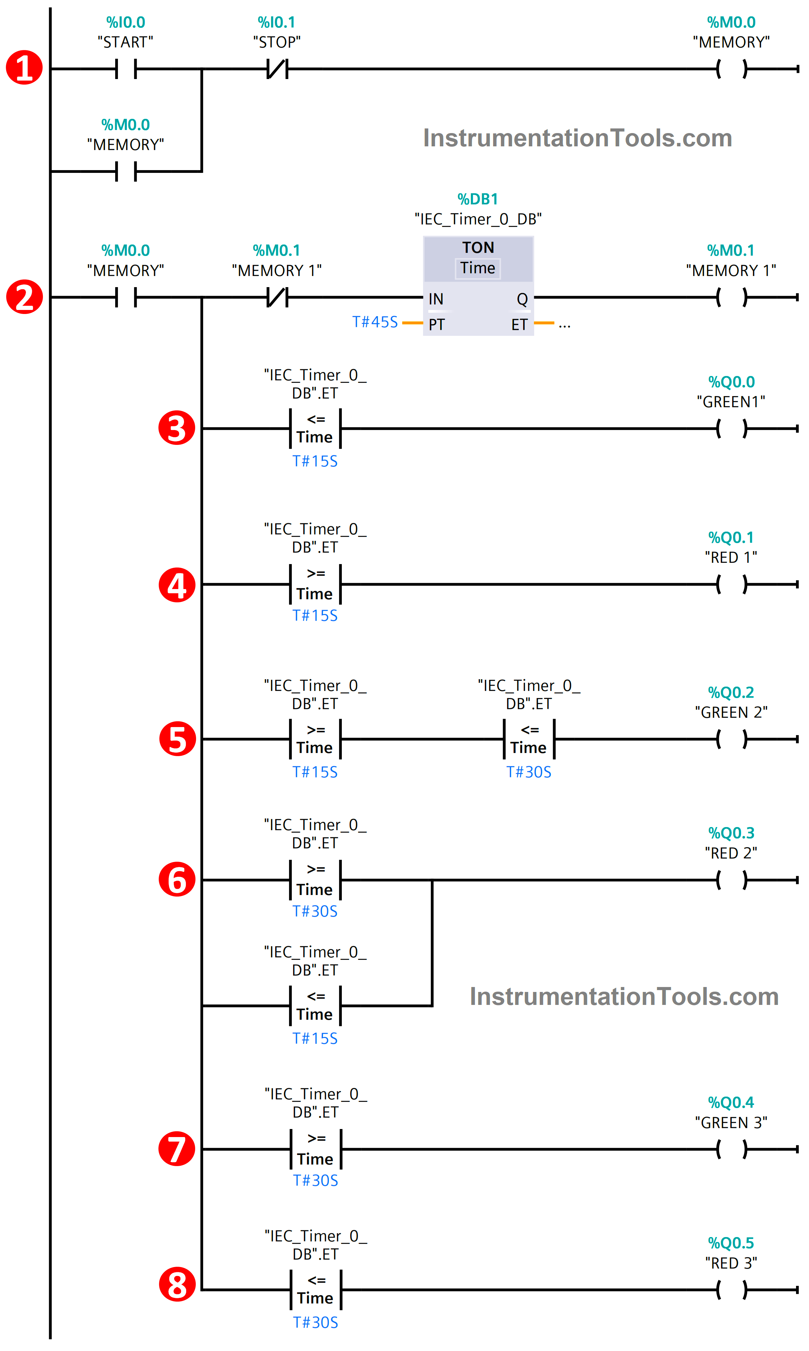
T-Junction Traffic Control System PLC Program

2. Once MEMORY is energized, it will switch on the TIMER DB1 which controls the timing of the Traffic Junction. In this timer, we set the Pre-set time of 45 seconds. Once the timer achieves the pre-set time which energizes the MEMORY 1 (M 0.1) and this M 0.1 also resets the timer as per the logic and runs the cycle continuously.

3. Next, the comparator plays a major role in controlling the traffic junction. Firstly, the Output GREEN 1 (Q 0.0) is turned on as per the logic. Here we used Less than or Equal to the comparator. In this logic, Q0.0 will be in the ON state from 0 seconds to 15 seconds. After that, it will be going to OFF state

4. Next for output RED 1 (Q0.1), we used Greater than or Equal to function. Q0.1 will be in the ON state from 15 seconds to 45 seconds. It will be in the OFF state when Q0.0 is in the ON state.

5. Then for output GREEN 2 (Q0.2), we used both Less than or Equal to and Greater than or Equal to for this output. Both the comparator functions were connected in series logic connection with the output. In this Q0.2 will be in the ON state from 16 seconds to 30 seconds as per the condition.

6. Next for output RED 2 (Q0.3), we also used both Less than or Equal to and Greater than or Equal to function for performing the operation. Comparators were connected in parallel connection with the output. This output will be in the ON state from 0 seconds to 15 seconds and 30 seconds to 45 seconds. In between 15 seconds, it will be in the OFF state only since at that time Q0.2 is in the ON state.

7. Then for the last GREEN 3 output (Q0.4), we used Greater than or Equal to function. As per the conditional logic, it will be in an ON state from 30 seconds to 45 seconds. Before this timing, it will be in an OFF state.

8. Finally, the RED 3 output (Q0.5). Here we used Less than or Equal to function for executing the PLC logic. It will be in the ON state from 0 seconds to 30 seconds after that it will be in the OFF state.

Conclusion

So, in this way, the given T-Junction Traffic control is executed by the comparator function with the PLC logic. We can control the traffic logic with the help of PLC logic in many ways & this is also one of the ways in that.

If are you interested to learn another approach for traffic light control using PLC, then watch the below video.

PLC Traffic Light Example Program - Red, Yellow, Green Lights

If you liked this article, then please subscribe to our YouTube Channel for Instrumentation, Electrical, PLC, and SCADA video tutorials.

You can also follow us on Facebook and Twitter to receive daily updates.

Read Next:

  • PLC Restrict Data Interfaces
  • Use PLC Flags as Integrity Checks
  • Offline and Online UPS Systems
  • Diagnostic Buffer for SIEMENS PLC
  • Modbus Driver for SCADA System
Don't Miss Our Updates
Be the first to get exclusive content straight to your email.
We promise not to spam you. You can unsubscribe at any time.
Invalid email address
You've successfully subscribed !

Continue Reading

Increment & Decrement Instructions in CX-Programmer (OMRON)
Industrial Networking and Wireless Interview Questions
PLC Timer Instructions
Electrical Cabinet Air Conditioner – Enclosure Cooling, Maintenance
Attendance System PLC Program using CX-Programmer
Parking Lights PLC Program Explained with Video
Share This Article
Facebook Whatsapp Whatsapp LinkedIn Copy Link
Share
Leave a Comment

Leave a Reply Cancel reply

Your email address will not be published. Required fields are marked *

Stay Connected

128.3kFollowersLike
69.1kFollowersFollow
210kSubscribersSubscribe
38kFollowersFollow

Categories

Explore More

How to do Scaling for Analog Input in RSLogix 500?
How to Create Templates in FactoryTalk View Studio?
#3 PLC Best Practices – Leave Operational Logic in the PLC wherever feasible
Chemical Mixing Process using PLC
Implement UDT in PLC Programming: User-Defined Data Type
How does SMPS Works? – Switched Mode Power Supply
PLC Batch System for 4 Tanks Mixing using CX-Programmer
Water Fountain Control Logic – PLC Exercises and Solutions

Keep Learning

Retrieve from memory card

How to Retrieve PLC Project From Memory Card?

PLC Automation for Product Weighing and Labeling

PLC Controlled Conveyor and Weighing with Labeling Automation

Overview of Industrial Control Systems

Overview of Industrial Control Systems

PLC Tag Naming Conventions

PLC Tag Naming Conventions

Simulating Level Sensor and the Pump Logic in PLC

PLC Basics – Manual Control, Closed Loop, ON-OFF with Hysteresis

Alarm prioritization

What is Alarm Prioritization? – Types of Alarms

PLC Commissioning and Testing

PLC Commissioning and Testing Procedure (Programmable Logic Controller)

PLC Program for Positive edge pulse output for one scan cycle

PLC Program for Positive Edge Pulse Output for One Scan Cycle

Learn More

Problem in Water Level Control System

Problem in Water Level Control System

What is Power Cable

What is Power Cable? Types of Power Cables

Digital Electronics MCQ

Binary Coded Decimal (BCD) Objective Questions

250+ Control System MCQ

250+ Control System MCQ Test Questions

control-valve-actuators

Control Valve Selection Tips

Burner Management System (BMS) Principle

What is Burner Management System (BMS)?

Geothermal Air Conditioners

Types of Air Conditioning Systems

Orifice Flow Meter With DP Transmitter

What is an Orifice Meter?

Menu

  • About
  • Privacy Policy
  • Copyright

Quick Links

  • Learn PLC
  • Helping Hand
  • Part Time Job

YouTube Subscribe

Follow US
All rights reserved. Reproduction in whole or in part without written permission is prohibited.
Welcome Back!

Sign in to your account

Username or Email Address
Password

Lost your password?