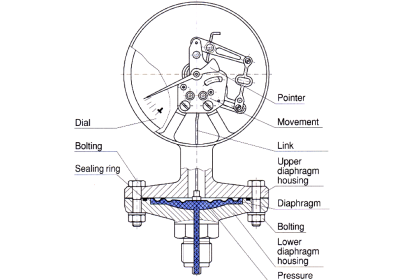
Symmetric capillary
1. Seal Effect:
If the ambient temperature increases the capillary volume V will tend to exert forces on the DP seal (both sides).
If both capillary have the same features (volume, seal thickness, fill fluid and length) are the same, all the resulting forces on the DP seal will be equal to zero (black DP seal position figure below).
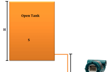
2. Hydrostatic Pressure:
The hydrostatic pressure figure below is P= ρ × g × D (where ρ and g are constants).
For the increase in ambient temperature, the density ρ will decrease.
This means the hydrostatic pressure P will decrease also. This will create an upper force (against the gravity force).
The resulting (final) DP seal position is shown in red figure below.

Figure – Symmetric capillary
Asymmetric Capillary
Hypothesis: The volume V1 << to V (V1 is negligible)
1. Seal Effect:
If the ambient temperature increases the capillary volume V will tend to exert forces on one side of the DP seal (blue DP seal position in below Figure).
2. Hydrostatic Pressure:
The hydrostatic pressure in Figure is P= ρ × g × D (where ρ and g are constants).
For the increase in ambient temperature, the density ρ will decrease.
This means that the hydrostatic pressure P will decrease also. This will create an upper force (against the gravity force). This will tend to compensate the seal effect force.
The resulting (final) DP seal position is shown in blue in Figure.

Figure – Asymmetric capillary
This asymmetric resulting force is inferior to the symmetric resulting force.
Limitation
Tall vessels and towers have posed a significant measurement challenge. In particular, long vertical tap‐to-tap distances require extended lengths of capillary to facilitate the installation.
As the tap‐to‐tap distance grows, the resulting head pressures within the capillary become too great to ‘tune’ out. Time‐response can be sub‐optimal on tall vessels and towers as the distance the pressure signal propagates through is substantially greater.
Overall, as the length of capillary attached to the transmitter low side increases, an accurate measurement becomes increasingly more difficult to achieve.


I need the details of Level switch at Mollass for the fermented wash.
Sir, can we download your informative articles for future reference? If yes then how?