In this article, we are going to discuss about shutter door control using induction motor and limit switches.
Shutter Door
Shutters are common type of doors used in all types of areas like residential, commercial, and industrial purposes. They are nothing but doors which have big openings for material movements and coverages. Shutters are opened or controlled by many methods like manually, mechanically, and electrically in industries.
Now, we are going to discuss about the controlling of shutters using electrical motors. Commonly, in industries, this method is only because there will be more movement of material supplies and it will be difficult if we follow manual or mechanical methods.
The electrical method was easy to control and saved more time than others.
Components Used
- 3 pole Miniature Circuit Breaker
- 3 Pole Contactors
- Start & Stop Buttons
- Limit switches
- Induction Motors
3 Pole Miniature Circuit Breaker
Miniature Circuit Breaker commonly known as MCB is used as the protective element for the system because it prevents the system from overcurrent and over voltage which will damage the actuating elements and other parts.
3 Pole Contactors
Contactors are the control elements that switch the supply to the actuating element from the control switches. In this, we used two contactors for forward and reverse control i.e., for Shutter up and down movements.
Start & Stop Buttons
Start and Stop buttons are used to initiate and pause the system and the Start button here is Up and Down buttons are used for control the up and down movement of the shutters.
Limit Switches
Limit switches are used to sense the end position on the system, here Up and Down limit switches are used to sense the end position on the top side and bottom side. Once the part touches the limit switches, the system will stop and it will not move beyond that.
Induction Motor
A three-phase motor is used to control the shutter movement Up and Down based on the control input.
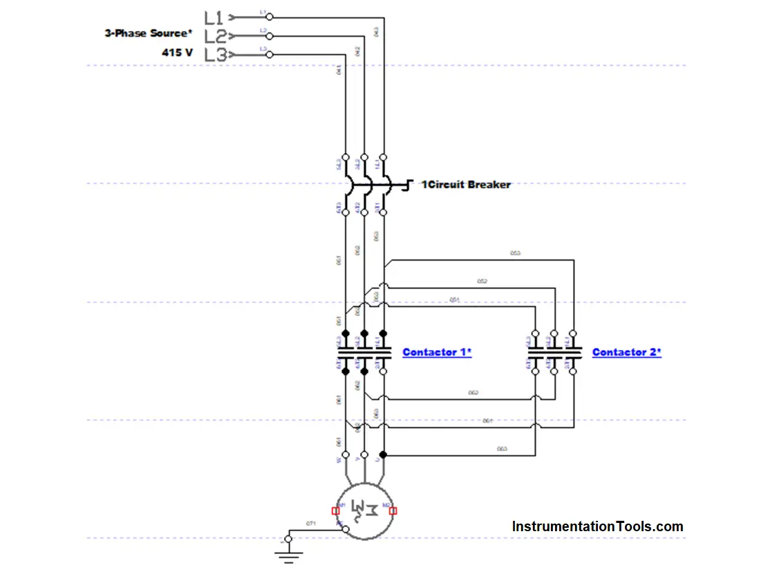
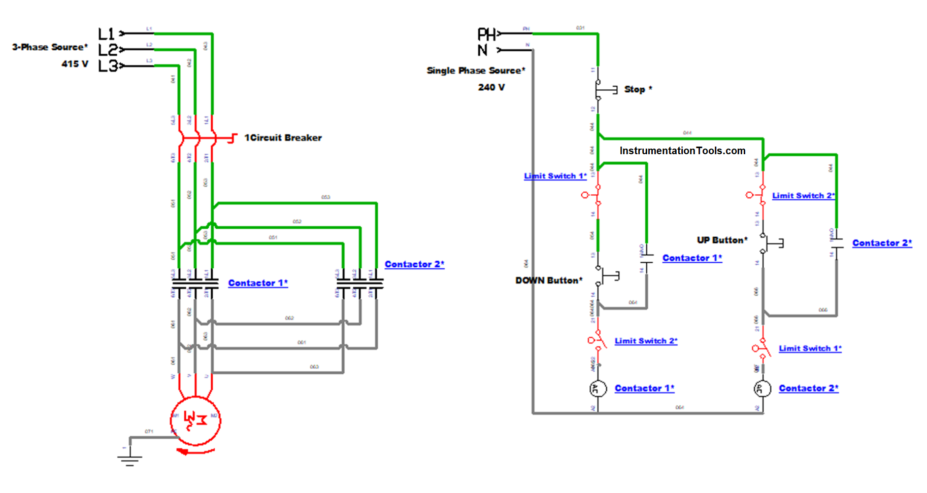
Power Circuit Diagram
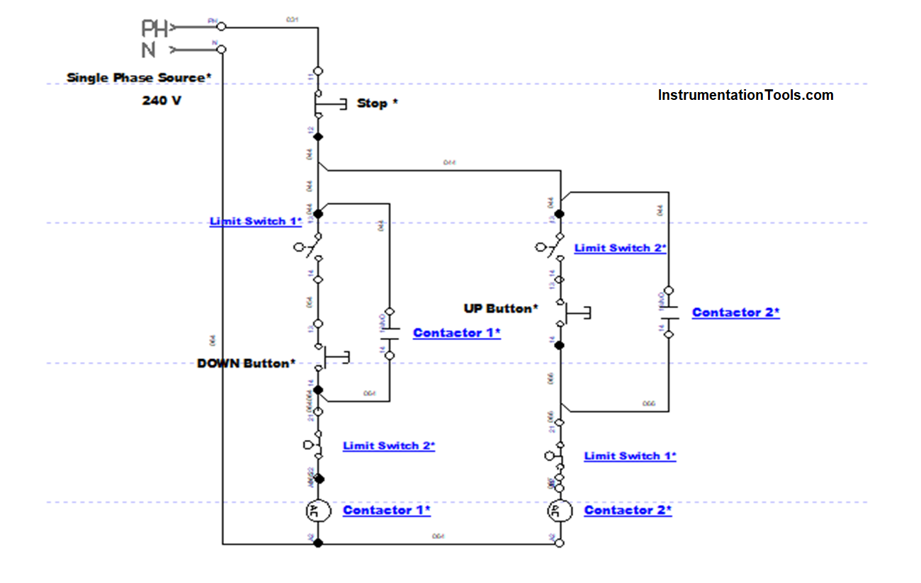
Control Circuit Diagram
Working Principle
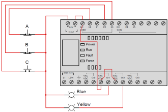
A three-Phase supply of 415 V is given to the power circuit and a Single-Phase supply of 240 V is given to the control circuit.
The power circuit consists of an MCB, Contactors, and a motor. The control circuit consists of Pushbuttons, limit switches, and contactor coils.
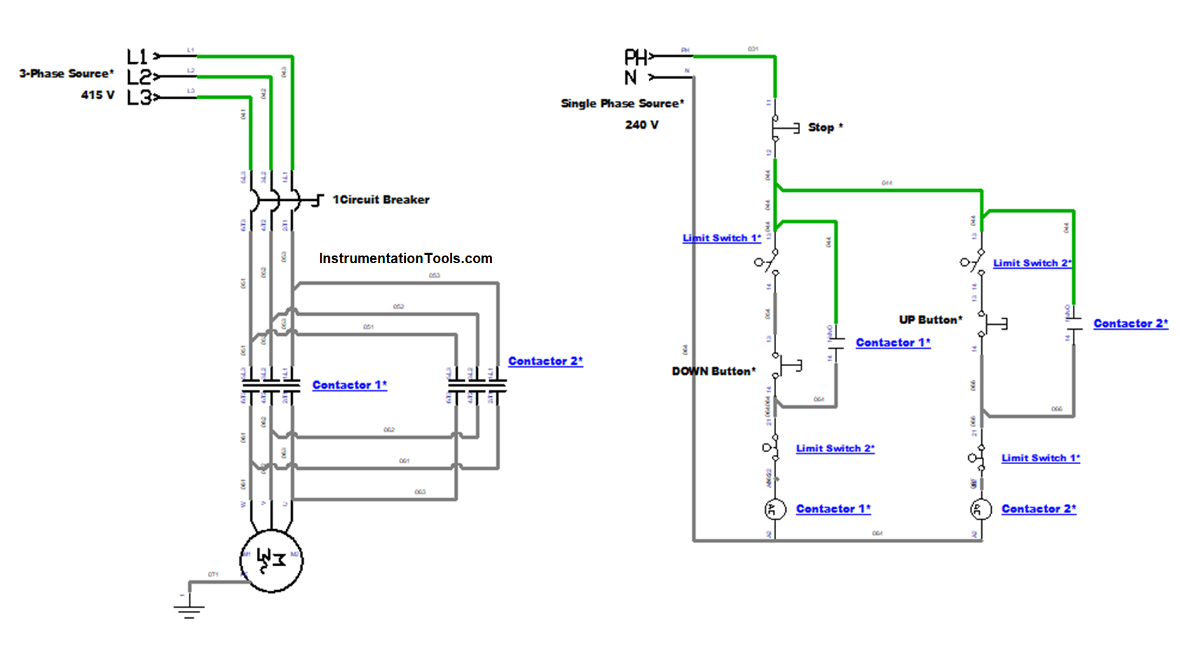
In the power circuit, the MCB is powered ON and the supply goes to the contactor and in the control circuit, the Shutter is on the top side so it makes contact with the Limit switch 1 (UP).
Then the Down button in the control circuit is pressed, which makes the Contactor 1 coil energize which makes the Contactor 1 activate, So the motor starts to rotate in a clockwise rotation. This means the shutter moves from top to bottom.
Once the shutter is moved from the top position, the limit switch 1 (UP) will get disconnected.
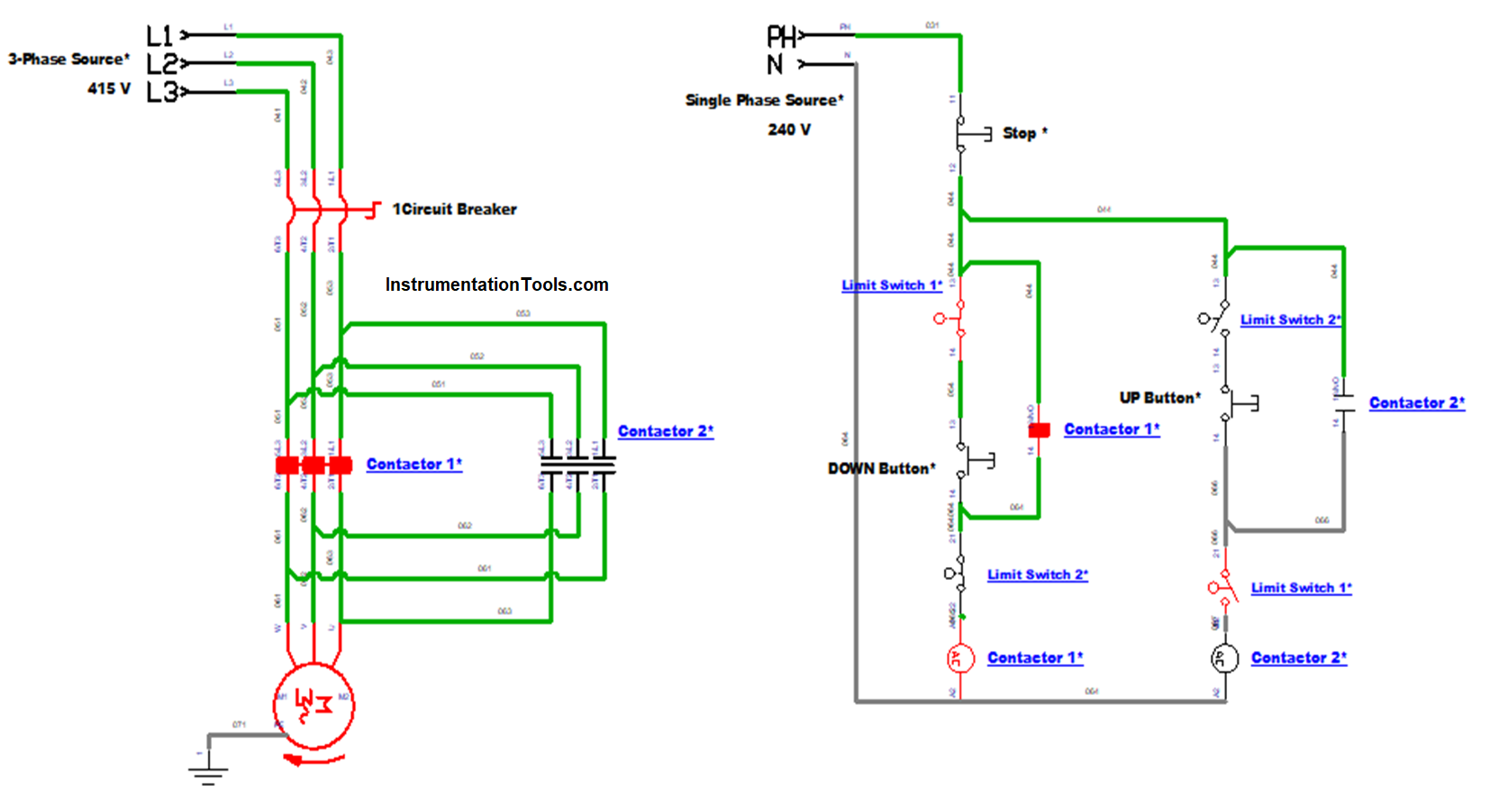
Once the shutter starts to move downwards, it will reach the endpoint at the down point and it will engage the limit switch 2 (DOWN) which will make the motor to stop rotating.
Now the shutter is on fully downwards, practically now it is in close position.
If we want to open the shutter, then the Up button in the control circuit is pressed. Since it is engaged with limit switch 2 (DOWN), it makes the Contactor 2 coil energize which makes the Contactor 2 activate.
So the motor starts to rotate this time in a counter-clockwise direction as we have reversed the two phases in the power circuit.
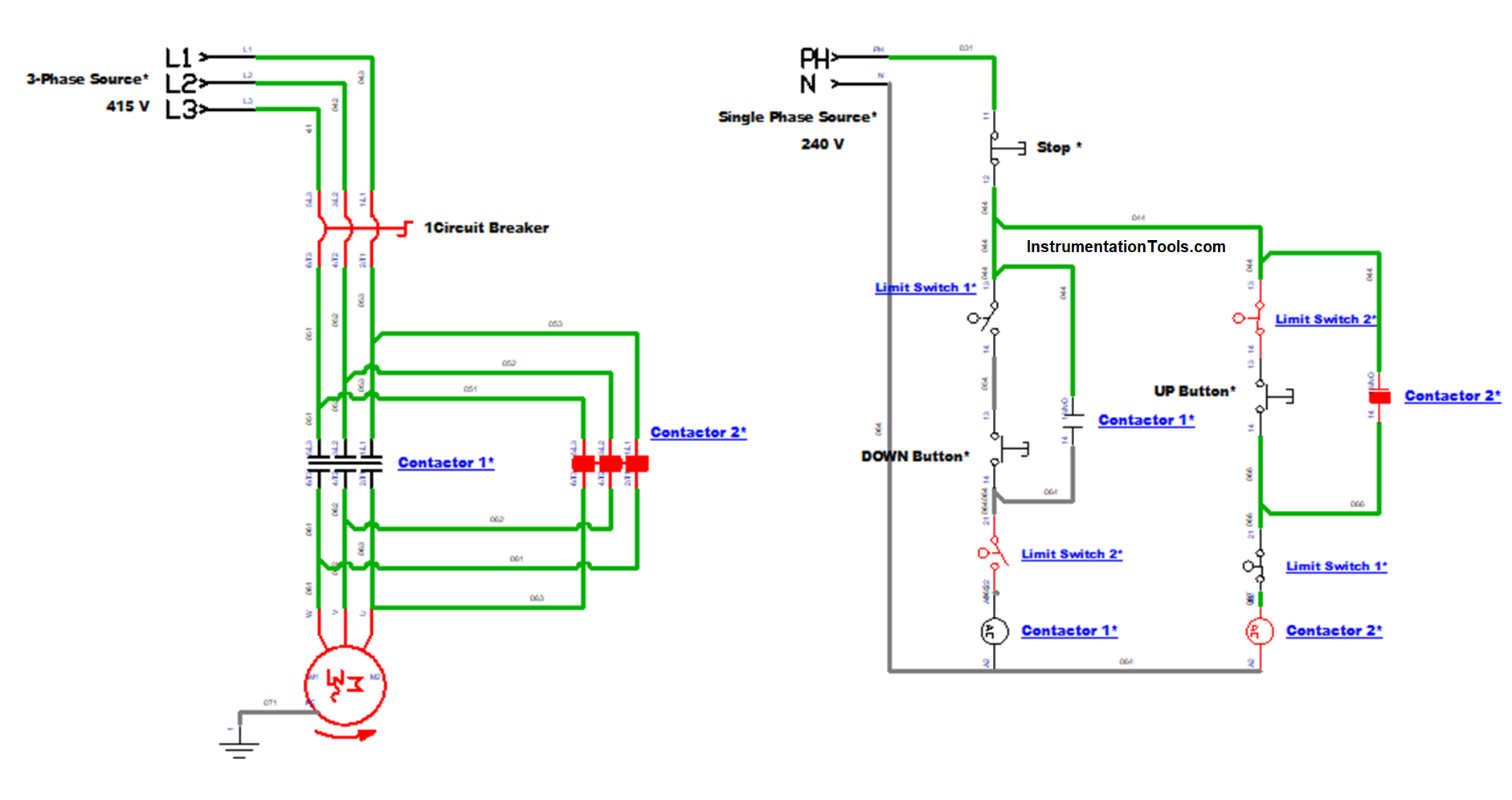
Now, the shutter moves upwards and at the end, it will engage with Limit switch 1 (UP) and cuts the connection which makes the motor rotation to stop.

Likewise, continuously we can control the Shutter movement with direction control of the motors with the help of limit switches and push buttons. If the stop push button is pressed all the function will be turned off instantly.
Conclusion
This is a typical control used for Shutter door movement in many areas of work. Since it has an easy mode of operation anyone can operate it in a safe manner and its servicing is also very easy. Because of its easy connection and control, it is one of the efficient and easy ways to control the shutter door.
Read Next:
- What is an Electrical Conduit?
- Single Core and Multi-Core Cables
- Difference Between HV and LV Cables
- Types of Cables in Industrial Automation
- Flame Resistant and Retardant Cables