Inst ToolsInst ToolsInst Tools
  • Courses
  • Automation
    • PLC
    • Control System
    • Safety System
    • Communication
    • Fire & Gas System
  • Instrumentation
    • Design
    • Pressure
    • Temperature
    • Flow
    • Level
    • Vibration
    • Analyzer
    • Control Valve
    • Switch
    • Calibration
    • Erection & Commissioning
  • Interview
    • Instrumentation
    • Electrical
    • Electronics
    • Practical
  • Q&A
    • Instrumentation
    • Control System
    • Electrical
    • Electronics
    • Analog Electronics
    • Digital Electronics
    • Power Electronics
    • Microprocessor
  • Request
Search
  • Books
  • Software
  • Projects
  • Process
  • Tools
  • Basics
  • Formula
  • Power Plant
  • Root Cause Analysis
  • Electrical Basics
  • Animation
  • Standards
  • 4-20 mA Course
  • Siemens PLC Course
Reading: Shift Bit Register in PLC
Share
Notification Show More
Font ResizerAa
Inst ToolsInst Tools
Font ResizerAa
  • Courses
  • Design
  • PLC
  • Interview
  • Control System
Search
  • Courses
  • Automation
    • PLC
    • Control System
    • Safety System
    • Communication
    • Fire & Gas System
  • Instrumentation
    • Design
    • Pressure
    • Temperature
    • Flow
    • Level
    • Vibration
    • Analyzer
    • Control Valve
    • Switch
    • Calibration
    • Erection & Commissioning
  • Interview
    • Instrumentation
    • Electrical
    • Electronics
    • Practical
  • Q&A
    • Instrumentation
    • Control System
    • Electrical
    • Electronics
    • Analog Electronics
    • Digital Electronics
    • Power Electronics
    • Microprocessor
  • Request
Follow US
All rights reserved. Reproduction in whole or in part without written permission is prohibited.
Inst Tools > Blog > PLC Tutorials > Shift Bit Register in PLC

Shift Bit Register in PLC

In this article, we will learn the concept of shift bit register in PLC programming including shift and rotate Instructions.

Last updated: May 17, 2023 12:00 pm
Viral Nagda
PLC Tutorials
No Comments
Share
6 Min Read
SHARE

There are many instructions in PLC that help in executing the logic in a simplified way. Instructions come in various categories like arithmetic, comparison, logical, controller, etc. For example, a simple addition instruction for adding two variables comes in the arithmetic category. So, similarly, many types of instructions are available in a PLC logic.

Contents
Shift Bit Register in PLCShift InstructionRotate Instruction

One such instruction which is widely used in PLC programming is shift instruction. It comes in the category of numerical processing.

In this article, we will learn the concept of shift bit register instruction in PLC programming.

Shift Bit Register in PLC

As the name implies, a shift instruction is a command for shifting bits of a word by some predefined position.

For example, you have a word of 16 bits. You want to move bit number 3 from its current fourth position to the seventh position. So, whenever a shift command pulse is given, the bit will shift in each trigger from the fourth position to the seventh position.

In that continuity, the bit in the fifth position will move to the eighth position; and the bit in the third position will move to the sixth position. So, here, you are shifting the bits in a group by the number of positions you define.

Shift Instruction

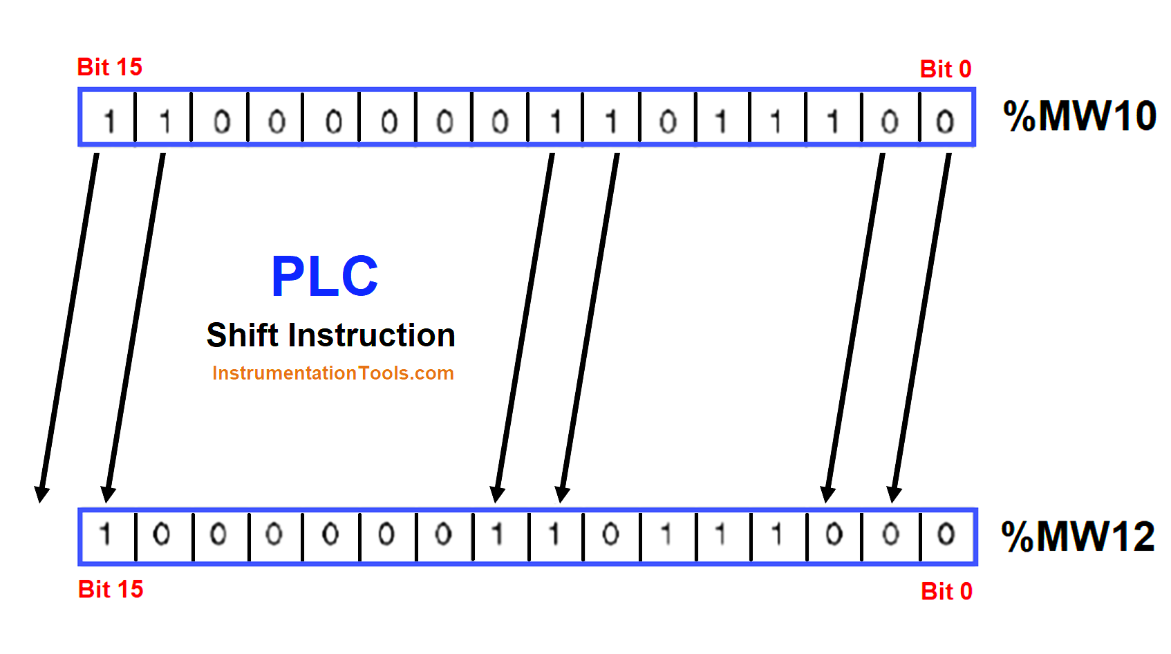
Shift instructions come in two types – shift and rotate. Let us have a look at the rotate instruction. Consider a syntax – %MW10:= SHL (%MW12, 4). %MW10 is the destination memory word and %MW12 is the source memory word.

Refer to the below image. In %MW10, when a first trigger for shift left is given, bit0 shifts to bit1, and so on. This result is stored in %MW12. When such triggers are given four times, ultimately, bit 0 will shift finally to bit 4, and so on.

The end result is stored in %MW12 anyways and you get a final answer of the bits shifted by four positions from the source word. But, one thing to remember is, with each shift, the preceding bit is filled with value 0. This you can see clearly in the image.

After the first shift, the first bit in %MW12 is 0. So, after four shifts, the end result will be – 0000 1101 1100 0000. This shift can thus be either right or left.

Shift Bit Register in PLC

One more type of shift comes in PLC; the earlier one added zeroes from the preceding position, but this second type keeps the value of the first bit (MSB for right and LSB for left) as it is. This is called arithmetic shifting.

So, if the value of the first bit (MSB for right and LSB for left) initially before the shift was 1, then the last bit will remain as 1 only and the zeroes will be added from the second preceding bit up to how many times the shift command is given. It is to be noted that the last bit which is shifted is always stored in a carry bit.

Rotate Instruction

The second type is rotate instruction. Consider the syntax – %MW10:= ROL (%MW12, 4). %MW10 is the destination memory word and %MW12 is the source memory word. We will use the same above image for reference. Rotate instruction, as the name defines, just rotates the bits by how many positions you define.

Compared to shift instruction where zero was added after every preceding bit; here, the bits are just shifted in the same sequence as it is in the left direction. So, suppose you have a source word of – 1100 1010 1100 0101; then, after a trigger of 4 positions, the end result will be – 1010 1100 0101 1100. The same logic works in the right direction. The last bit shifted is also stored in a carry bit.

One more type comes in the rotate category. Here, instead of shifting only 16 bits, the carry bit to is rolled over. This means, the last bit is shifted to the carry bit, and the carry bit will then be shifted to the first bit, and so on. In the earlier type, the last bit was only stored in the carry bit.

If you liked this article, then please subscribe to our YouTube Channel for Instrumentation, Electrical, PLC, and SCADA video tutorials.

You can also follow us on Facebook and Twitter to receive daily updates.

Read Next:

  • Find the Best PLC for Your Project
  • HMI Screens on a Mobile or Tablet
  • Top Automation Vendors in World
  • Tia Portal Interrupt Organization Block
  • Types of Sensors Used in Automobiles
Don't Miss Our Updates
Be the first to get exclusive content straight to your email.
We promise not to spam you. You can unsubscribe at any time.
Invalid email address
You've successfully subscribed !

Continue Reading

Create Logic with InTouch Scada using Scripting
Function Block (FB) for Motor Control Logic
Best Way to Build Troubleshooting Mindset for Automation Engineer
Configuration of Siemens VFD Using TIA Portal Start drive
PLC Sequential Operation Example Program
What is Fail-safe in Siemens PLC?
Share This Article
Facebook Whatsapp Whatsapp LinkedIn Copy Link
Share
Leave a Comment

Leave a Reply Cancel reply

Your email address will not be published. Required fields are marked *

Stay Connected

128.3kFollowersLike
69.1kFollowersFollow
210kSubscribersSubscribe
38kFollowersFollow

Categories

Explore More

What are Analog and Digital Signals? Differences, Examples
PLC 1 Push Button to Turn ON or OFF 1 Output
Free InTouch SCADA Tutorial Course for Beginners
Site Commissioning Steps for PLC Programmers
How to Delete the Siemens CPU Memory?
OPC in Old PLC Systems
Example PLC Program
PLC Programming for Sequential Batch Mixing System

Keep Learning

Human Machine Interface

What is Human Machine Interface (HMI) ?

LED Indications on PLC

Getting to Know the LED Indications on GE Make PLC

PLC Program to Control Gas Pressure using Closed-Loop

PLC Program to Control Gas Pressure using Closed-Loop

Motor Library in Studio 5000 PLC

Create User-Defined Data Types and Function Blocks in Studio 5000

Laws of Boolean Algebra using Ladder Logic

Laws of Boolean Algebra using Ladder Logic

PC-Based Motion Controller

Various Types of Delta PLC used in Industrial Automation

Types of Switches

Electrical Switches Principle & Types

OB and FB Blocks in Siemens PLC

Procedure for Siemens S7-300 Download from PC to PLC

Learn More

Thermocouple Temperature Range

Thermocouple Properties, Temperature Ranges, Element Construction

Emergency Shutdown System

What is Emergency Shutdown System (ESD) ?

State Variable Analysis and Design

State Variables & Linear Discrete Time Systems

Mass Spectrometer Questions and Answers

Surface Spectroscopic Techniques

Flame Emission Photometers Questions & Answers

Flame Emission Photometers Questions & Answers

Elevator PLC Ladder Logic

Elevator PLC Ladder Logic

Short Notes on Rectifiers & Filters

Short Notes on Rectifiers & Filters

Ultrasonic Tank Gauging

Ultrasonic Tank Gauging

Menu

  • About
  • Privacy Policy
  • Copyright

Quick Links

  • Learn PLC
  • Helping Hand
  • Part Time Job

YouTube Subscribe

Follow US
All rights reserved. Reproduction in whole or in part without written permission is prohibited.
Welcome Back!

Sign in to your account

Username or Email Address
Password

Lost your password?