If a liquid flow-control valve is opened in a step-change fashion, flow through the pipe tends to self-stabilize at a new rate very quickly.
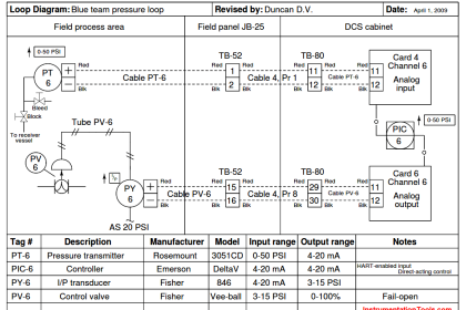
The following illustration shows a typical liquid flow-control installation, with a process trend showing the flow response following a manual-mode (also known as “open-loop”) step-change in valve position:


The defining characteristic of a self-regulating process is its inherent ability to settle at a new process variable value without any corrective action on the part of the controller. In other words, a self-regulating process will exhibit a unique process variable value for each possible output (valve) value.
The inherently fast response of a liquid flow control process makes its self-regulating nature obvious: the self-stabilization of flow generally takes place within a matter of seconds following the valve’s motion.
Many other processes besides liquid flow are self-regulating as well, but their slow response times require patience on the part of the observer to tell that the process will indeed self-stabilize following a step-change in valve position.
Also Read : On/off Control Theory
A corollary to the principle of self-regulation is that a unique output value will be required to achieve a new process variable value.
For example, to achieve a greater flow rate, the control valve must be opened further and held at that further-open position for as long as the greater flow rate is desired. This presents a fundamental problem for a proportional-only controller.
Recall the formula for a proportional-only controller, defining the output value (m) by the error (e) between process variable and setpoint multiplied by the gain (Kp ) and added to the bias (b):
m = Kp e + b
Where,
m = Controller output
e = Error (difference between PV and SP)
Kp = Proportional gain
b = Bias
Suppose we find the controller in a situation where there is no error (PV = SP), and the flow rate is holding steady at some value. If we then increase the setpoint value (calling for a greater flow rate), the error will increase, driving the valve further open.
As the control valve opens further, flow rate naturally increases to match. This increase in process variable drives the error back toward zero, which in turn causes the controller to decrease its output value back toward where it was before the setpoint change.
However, the error can never go all the way back to zero because if it did, the valve would return to its former position, and that would cause the flow rate to self-regulate back to its original value before the setpoint change was made.
What happens instead is that the control valve begins to close as flow rate increases, and eventually the process finds some equilibrium point where the flow rate is steady at some value less than the setpoint, creating just enough error to drive the valve open just enough to maintain that new flow rate.
Unfortunately, due to the need for an error to exist, this new flow rate will fall shy of our setpoint. We call this error proportional-only offset, or droop, and it is an inevitable consequence of a proportional-only controller attempting to control a self-regulating process.
For any fixed bias value, there will be only one setpoint value that is perfectly achievable for a proportional-only controller in a self-regulating process.
Any other setpoint value will result in some degree of offset in a self-regulating process. If dynamic stability is more important than absolute accuracy (zero offset) in a self-regulating process, a proportional-only controller may suffice.
A great many self-regulating processes in industry have been and still are controlled by proportional-only controllers, despite some inevitable degree of offset between PV and SP.
The amount of offset experienced by a proportional-only controller in a self-regulating process may be minimized by increasing the controller’s gain. If it were possible to increase the gain of a proportional-only controller to infinity, it would be able to achieve any setpoint desired with zero offset!
However, there is a practical limit to the extent we may increase the gain value, and that limit is oscillation. If a controller is configured with too much gain, the process variable will begin to oscillate over time, never stabilizing at any value at all, which of course is highly undesirable for any automatic control system.
Even if the gain is not great enough to cause sustained oscillations, excessive values of gain will still cause problems by causing the process variable to oscillate with decreasing amplitude for a period of time following a sudden change in either setpoint or load.
Determining the optimum gain value for a proportional-only controller in a self-regulating process is, therefore, a matter of compromise between excessive offset and excessive oscillation.
Recall that the purpose of integral (or “reset”) control action was the elimination of offset. Integral action works by ramping the output of the controller at a rate determined by the magnitude of the offset: the greater the difference between PV and SP for an integral controller, the faster that controller’s output will ramp over time.
In fact, the output will stabilize at some value only if the error is diminished to zero (PV = SP). In this way, integral action works tirelessly to eliminate offset.
Also Read : Feedback Control Principle
It stands to reason then that a self-regulating process absolutely requires some amount of integral action in the controller in order to achieve zero offset for all possible setpoint values.
The more aggressive (faster) a controller’s integral action, the sooner offset will be eliminated. Just how much integral action a self-regulating process can tolerate depends on the magnitudes of any time lags in the system.
The faster a process’s natural response is to a manual step-change in controller output, the better it will respond to aggressive integral controller action once the controller is placed in automatic mode. Aggressive integral control action in a slow process, however, will result in oscillation due to integral wind-up (Note 1 ).
It is not uncommon to find self-regulating processes being controlled by integral-only controllers. An “integral-only” process controller is an instrument lacking proportional or derivative control modes. Liquid flow control is a nearly ideal candidate process for integral-only control action, due to its self-regulating and fast-responding nature.
Note 1 : Recall that wind-up is what happens when integral action “demands” more from a process than the process can deliver. If integral action is too aggressive for a process (i.e. fast integral controller action in a process with slow time lags), the output will ramp too quickly, causing the process variable to overshoot setpoint which then causes integral action to wind the other direction. As with proportional action, too much integral action will cause a self-regulating process to oscillate.
Summary :
- Self-regulating processes are characterized by their natural ability to stabilize at a new process variable value following changes in the control element value or load(s).
- Self-regulating processes absolutely require integral controller action to eliminate offset between process variable and setpoint, because only integral action is able to create a different controller output value once the error returns to zero.
- Faster integral controller action results in quicker elimination of offset.
- The amount of integral controller action tolerable in a self-regulating process depends on the degree of time lag in the system. Too much integral action will result in oscillation, just like too much proportional control action.
Also Read : PID Controller Loop Tuning