SAMA is an acronym of Scientific Apparatus Makers Association, in some plants, there has been greater adoption of SAMA diagrams which provide more detailed process diagrams which constitute various process symbols.
SAMA drawings are sometimes referred to as “control functional diagrams”.
SAMA symbols are rarely used on P&IDs. Rather, they are generally used to diagram control systems at a detailed functional level. They provide no information about the device’s location or function, nor about the technology used to implement it.
SAMA Diagram
Usually, SAMA symbols show the control system without reference to the processing equipment or piping details. Still, for complex control systems, because they can show greater functionality compared with other documentation formats, they are often preferred for presenting control strategy details in some industries.
Because of the complexity of their control strategies, SAMA symbols are extensively used in the power generation industry. SAMA methods tend to be used for boiler functional diagrams due to the higher level of control-element details and the visualization they provide.
The newer ANSI (American National Standards Institute) symbols have similarities and differences and are used in many industries. The International Society of Automation (ISA) standards are another choice for putting forward control diagrams.
Many manufacturers of control equipment, particularly distributed control systems (DCS), document their library of control algorithms using something similar to SAMA symbology.
The below figure shows the basic control loop that illustrates SAMA symbols.
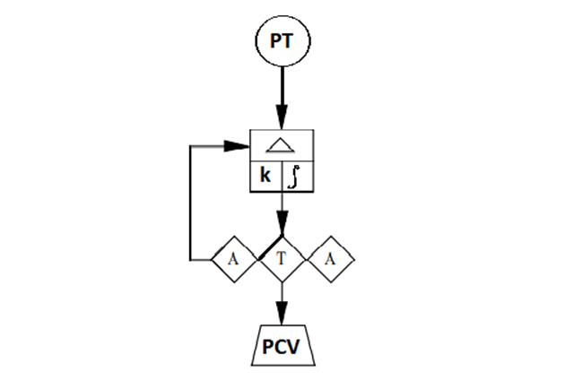
In the above drawing, the three diamonds grouped together represent the adjustable setpoint (left A), the adjustable manual output (right A), the auto/manual transfer switch (T).
The square-shaped box is a controller. The diamond-shaped enclosures denote that these are all manual functions performed by the operator.
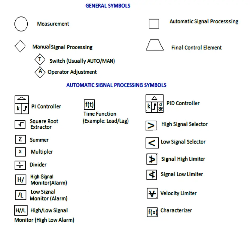
The figure below is an abbreviated list of some of the commonly used symbols.
ISA and SAMA Diagrams
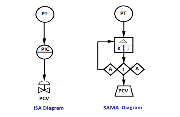
The below figure shows a simplified example using both ISA and its equivalent SAMA functional diagram.
Generally, the ISA symbology tends to be better suited for piping and instrumentation diagrams (P&IDs), while the SAMA diagrams are better suited to indicate complex logic functions and control.
Three Element Drum Level Control
A three-element control loop is an important application in boiler control. Boiler drum level is a critical process variable (PV) in the safe operation of a boiler.
The below figure is a SAMA diagram of the cascade plus feedforward control application approach.
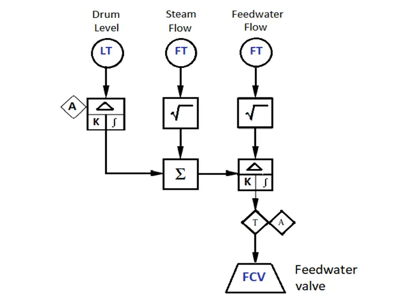
The three transmitters are the three elements referred to in the name of the control system. The feedwater flow setpoint is automatically by the steam flow signal to keep the feed water supply in balance with the steam demand. This is the feed water component of the control methodology.
The drum level controller trims the feedwater flow setpoint to compensate for errors in the flow measurements or any other unmeasured load disturbances such as blowdown that may affect the drum level. This is the cascade component of the control scheme.
The summing function is employed to combine these two components. The square root functions on the flow transmitters linearize the relationship between the flow and differential pressure flow meters.
Interest to read more example and symbols of SAMA? then download the below document.
| Title: | Functional Diagrams of Instrument and Control Systems |
| Author: | MCAA |
| Format: | |
| Size: | 641 KB |
| Pages: | 29 |
| Download: | Click Here |
If you liked this article, then please subscribe to our YouTube Channel for Instrumentation, PLC, and SCADA video tutorials.
You can also follow us on Facebook and Twitter to receive daily updates.
Read Next:
