This article discusses about Retentive ON Delay Timer instruction and working principle using Allen Bradley Programmable Logic Controller (PLC) Ladder Logic.
Retentive ON delay timer

In the above Retentive ON Delay Timer, there are totally four parameter,
TIMER: T4:0 – Timer File name (Timer T4:0, T4:1, T4:2…)
TIMER BASE – How the time need to count, in Seconds, Milli Seconds…
PRESET – Limit value of Timer-Up to how much it should count
ACCUMULATOR – Running Value of timer when it is in ON condition.
Program Description:
Retentive ON delay timer is to delaying the ON time, if input goes off in between, it will resumes the accumulator value and input turns ON, it will start running for the resumed value.
Example-VLC video player plays video from the resumed placed if we closed and open the player again.

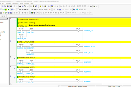
Retentive ON delay timer using PLC

RUNG 0000:
Start and Stop Switch is to turn ON/OFF the timer.
RUNG 0001:
When start switch is pressed, Timer Enable bit (T4:0/EN) is turned ON to show the status of TIMER ON/OFF condition
RUNG 0002 :
When start switch is pressed, along with the timer enable bit timer timing bit also turned ON to show the status of timer’s accumulator (T4:0/ACC)value is currently in running state.
RUNG 0003:
When start switch is pressed, timer starts running from zero to preset valve, timer’s done bit is turned ON when accumulator value reached preset value.
Notes: Reset is done automatically in this program to run the program continuously.
Conclusion
We can use this example program to understand the working of Retentive ON delay timer function in Allen Bradley PLC.
Author : Hema Sundaresan
If you liked this article, then please subscribe to our YouTube Channel for PLC and SCADA video tutorials.
You can also follow us on Facebook and Twitter to receive daily updates.
Read Next:


Can u say me the ans of explain operation of retentive on delay timer function using timming diagram
Explain PLC S7 Siemens