Inst ToolsInst ToolsInst Tools
  • Courses
  • Automation
    • PLC
    • Control System
    • Safety System
    • Communication
    • Fire & Gas System
  • Instrumentation
    • Design
    • Pressure
    • Temperature
    • Flow
    • Level
    • Vibration
    • Analyzer
    • Control Valve
    • Switch
    • Calibration
    • Erection & Commissioning
  • Interview
    • Instrumentation
    • Electrical
    • Electronics
    • Practical
  • Q&A
    • Instrumentation
    • Control System
    • Electrical
    • Electronics
    • Analog Electronics
    • Digital Electronics
    • Power Electronics
    • Microprocessor
  • Request
Search
  • Books
  • Software
  • Projects
  • Process
  • Tools
  • Basics
  • Formula
  • Power Plant
  • Root Cause Analysis
  • Electrical Basics
  • Animation
  • Standards
  • 4-20 mA Course
  • Siemens PLC Course
Reading: Resistance Temperature Detectors (RTD) Construction
Share
Font ResizerAa
Inst ToolsInst Tools
Font ResizerAa
  • Courses
  • Design
  • PLC
  • Interview
  • Control System
Search
  • Courses
  • Automation
    • PLC
    • Control System
    • Safety System
    • Communication
    • Fire & Gas System
  • Instrumentation
    • Design
    • Pressure
    • Temperature
    • Flow
    • Level
    • Vibration
    • Analyzer
    • Control Valve
    • Switch
    • Calibration
    • Erection & Commissioning
  • Interview
    • Instrumentation
    • Electrical
    • Electronics
    • Practical
  • Q&A
    • Instrumentation
    • Control System
    • Electrical
    • Electronics
    • Analog Electronics
    • Digital Electronics
    • Power Electronics
    • Microprocessor
  • Request
Follow US
All rights reserved. Reproduction in whole or in part without written permission is prohibited.
Inst Tools > Blog > Temperature Measurement > Resistance Temperature Detectors (RTD) Construction

Resistance Temperature Detectors (RTD) Construction

Last updated: June 2, 2018 10:16 pm
Editorial Staff
Temperature Measurement
No Comments
Share
4 Min Read
SHARE

The RTD incorporates pure metals or certain alloys that increase in resistance as temperature increases and, conversely, decrease in resistance as temperature decreases. RTDs act somewhat like an electrical transducer, converting changes in temperature to voltage signals by the measurement of resistance. The metals that are best suited for use as RTD sensors are pure, of uniform quality, stable within a given range of temperature, and able to give reproducible resistance-temperature readings. Only a few metals have the properties necessary for use in RTD elements.

RTD elements are normally constructed of platinum, copper, or nickel. These metals are best suited for RTD applications because of their linear resistance-temperature characteristics (as shown in Figure 1), their high coefficient of resistance, and their ability to withstand repeated temperature cycles.

Electrical Resistance Temperature Curves of RTD

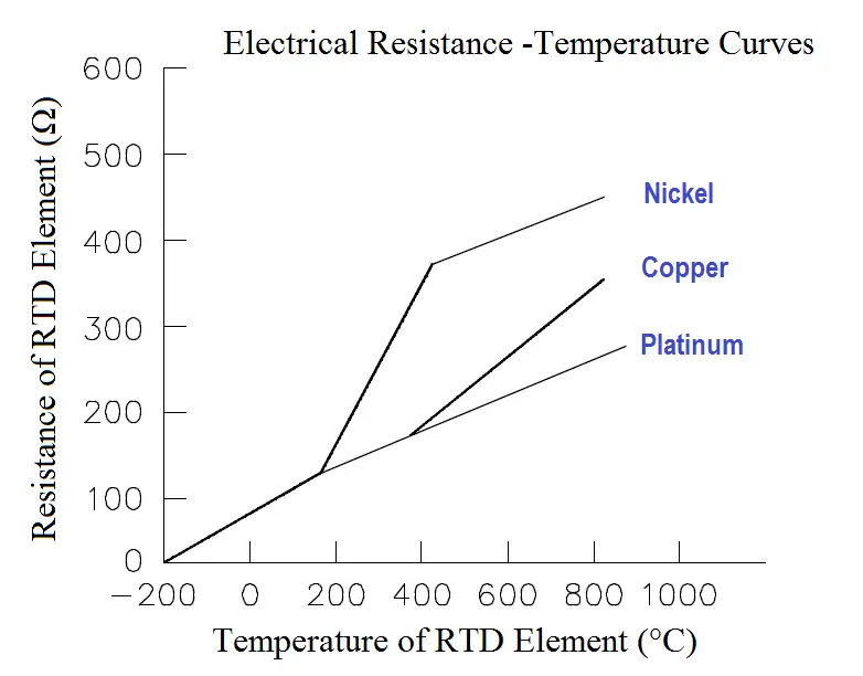
Figure 1 Electrical Resistance-Temperature Curves

The coefficient of resistance is the change in resistance per degree change in temperature, usually expressed as a percentage per degree of temperature. The material used must be capable of being drawn into fine wire so that the element can be easily constructed.

RTD elements are usually long, spring-like wires surrounded by an insulator and enclosed in a sheath of metal. Figure 2 shows the internal construction of an RTD.

RTD Construction

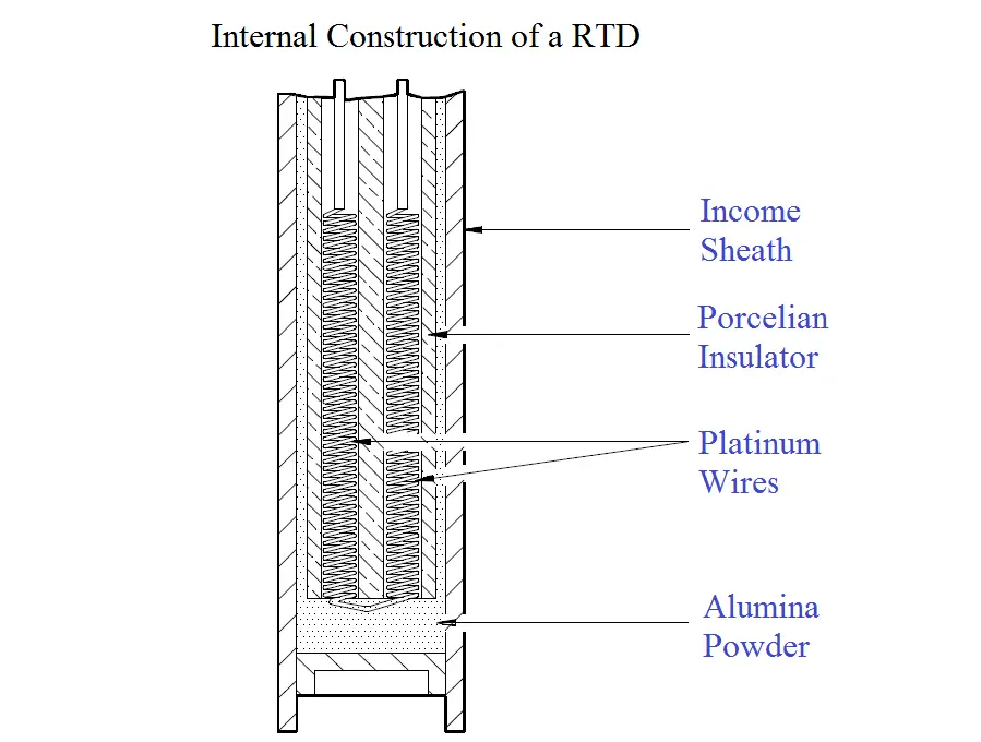
Figure 2 Internal Construction of a Typical RTD

This particular design has a platinum element that is surrounded by a porcelain insulator. The insulator prevents a short circuit between the wire and the metal sheath.

Inconel, a nickel-iron-chromium alloy, is normally used in manufacturing the RTD sheath because of its inherent corrosion resistance. When placed in a liquid or gas medium, the Inconel sheath quickly reaches the temperature of the medium. The change in temperature will cause the platinum wire to heat or cool, resulting in a proportional change in resistance.

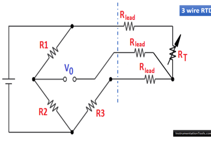
This change in resistance is then measured by a precision resistance measuring device that is calibrated to give the proper temperature reading. This device is normally a bridge circuit.

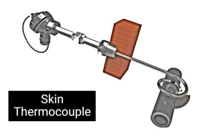
Figure 3 shows an RTD protective well and terminal head. The well protects the RTD from damage by the gas or liquid being measured. Protecting wells are normally made of stainless steel, carbon steel, Inconel, or cast iron, and they are used for temperatures up to 1100°C.

RTD Protective Well and Terminal Head
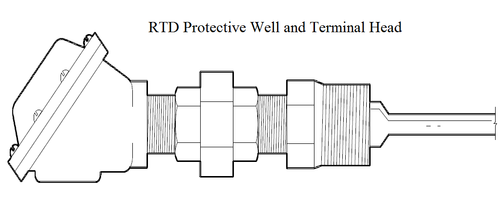
Figure 3 RTD Protective Well and Terminal Head

Summary

Resistance temperature detectors (RTDs) are summarized below.

1. The resistance of an RTD varies directly with temperature:

  • As temperature increases, resistance increases.
  • As temperature decreases, resistance decreases.

2. RTDs are constructed using a fine, pure, metallic, spring-like wire surrounded by an insulator and enclosed in a metal sheath.

3. A change in temperature will cause an RTD to heat or cool, producing a proportional change in resistance. The change in resistance is measured by a precision device that is calibrated to give the proper temperature reading.

Don't Miss Our Updates
Be the first to get exclusive content straight to your email.
We promise not to spam you. You can unsubscribe at any time.
Invalid email address
You've successfully subscribed !

Continue Reading

18 Temperature Sensors Fault Leads to Plant Shutdown
Temperature Measurement Objective Questions
Resistance Temperature Detectors Working Principle
Manually Interpreting Thermocouple Voltages
Bridge Circuit Construction
Distributed Temperature Sensors (DTS) in Power Lines
Share This Article
Facebook Whatsapp Whatsapp LinkedIn Copy Link
Share
Leave a Comment

Leave a Reply Cancel reply

Your email address will not be published. Required fields are marked *

Stay Connected

128.3kFollowersLike
69.1kFollowersFollow
210kSubscribersSubscribe
38kFollowersFollow

Categories

Explore More

Why have been limits imposed on the frequency ratio for thermowells?
Response Time Test of RTD and Thermocouple
Thermocouple Working Principle
Free Download Thermocouple Calculator
Basics of Temperature Switch
Thermistor Working Principle
What are the Thermocouple Applications?
Thermocouple Details

Keep Learning

Thermowell Design Guidelines

Thermowell Outer Diameter larger than Nozzle Inside Diameter

Thermowell Outer Diameter Larger than Nozzle Inside Diameter?

Formula of 2 Wire RTD, 3 Wire RTD & 4 Wire RTD

Formula of 2 Wire RTD, 3 Wire RTD & 4 Wire RTD

How to Install Thermowell on an Elbow?

Three Wire RTD Wheatstone bridge Circuit

RTD Wheatstone Bridge Circuits

Head Mount Temperature Transmitter

What is a Head Mount Temperature Transmitter? – Advantages

Temperature Switch Symbol

Temperature Switch Principle

Temperature Sensor Failure

Temperature Sensor Failure

Learn More

Unbalanced Bridge Circuit

Bridge Circuit Construction

PM of Instrument Air Compressor

PM of Instrument Air Compressor in Oil & Gas Plants

Instrumentation Design Engineer

Role of an Instrumentation Design Engineer for Beginners

Digital Electronics Multiple Choice Questions

Number Systems Objective Questions

OTDR testing

OTDR Testing

PLC Programmer Salary and Future Career Scope

PLC Programmer Salary and Future Career Scope

Electrical Torsion Meter

Electrical Torsion Meter Principle

Transmitter Identification Codes

Instrument Identification Tags

Menu

  • About
  • Privacy Policy
  • Copyright

Quick Links

  • Learn PLC
  • Helping Hand
  • Part Time Job

YouTube Subscribe

Follow US
All rights reserved. Reproduction in whole or in part without written permission is prohibited.
Welcome Back!

Sign in to your account

Username or Email Address
Password

Lost your password?