Inst ToolsInst ToolsInst Tools
  • Courses
  • Automation
    • PLC
    • Control System
    • Safety System
    • Communication
    • Fire & Gas System
  • Instrumentation
    • Design
    • Pressure
    • Temperature
    • Flow
    • Level
    • Vibration
    • Analyzer
    • Control Valve
    • Switch
    • Calibration
    • Erection & Commissioning
  • Interview
    • Instrumentation
    • Electrical
    • Electronics
    • Practical
  • Q&A
    • Instrumentation
    • Control System
    • Electrical
    • Electronics
    • Analog Electronics
    • Digital Electronics
    • Power Electronics
    • Microprocessor
  • Request
Search
  • Books
  • Software
  • Projects
  • Process
  • Tools
  • Basics
  • Formula
  • Power Plant
  • Root Cause Analysis
  • Electrical Basics
  • Animation
  • Standards
  • 4-20 mA Course
  • Siemens PLC Course
Reading: Current Divider Rule
Share
Notification Show More
Font ResizerAa
Inst ToolsInst Tools
Font ResizerAa
  • Courses
  • Design
  • PLC
  • Interview
  • Control System
Search
  • Courses
  • Automation
    • PLC
    • Control System
    • Safety System
    • Communication
    • Fire & Gas System
  • Instrumentation
    • Design
    • Pressure
    • Temperature
    • Flow
    • Level
    • Vibration
    • Analyzer
    • Control Valve
    • Switch
    • Calibration
    • Erection & Commissioning
  • Interview
    • Instrumentation
    • Electrical
    • Electronics
    • Practical
  • Q&A
    • Instrumentation
    • Control System
    • Electrical
    • Electronics
    • Analog Electronics
    • Digital Electronics
    • Power Electronics
    • Microprocessor
  • Request
Follow US
All rights reserved. Reproduction in whole or in part without written permission is prohibited.
Inst Tools > Blog > Electronic Devices & Circuits > Current Divider Rule

Current Divider Rule

Last updated: October 6, 2016 6:39 am
Editorial Staff
Electronic Devices & Circuits
No Comments
Share
1 Min Read
SHARE

It can be quite useful to determine how a current entering two parallel resistors “divides” between them.

Consider the circuit shown below:

Current Divider Rule

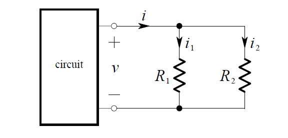
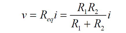
We replace the parallel connection of R1   and R2  by its equivalent resistance.

Thus, Ohm’s Law gives:

current-divider-rule-equation

By application of Ohm’s Law again, the current in R1  is i1  = v R1 and thus:

current-divider-rule-formula

Similarly, the current in R2 is :

current-divider-rule-formula-new

These equations describe how the current is divided between the resistors. Because of this, a pair of resistors in parallel is often called a current divider. Note that a larger amount of current will exist in the smaller resistor – thus current tends to take the path of least resistance!
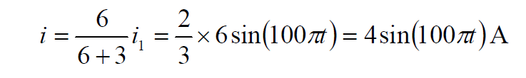
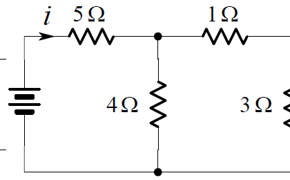
Example:

We want to find the current i in the circuit below:

current-divider-rule-circuit

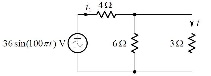
The total current delivered by the source is:

current-divider-rule-equation-2

Therefore the desired current is:

current-divider-rule-equation-3

Don't Miss Our Updates
Be the first to get exclusive content straight to your email.
We promise not to spam you. You can unsubscribe at any time.
Invalid email address
You've successfully subscribed !

Continue Reading

Seven Segment Display Working Principle
Transistor Amplifier Working Principle
Dependent Current Source
Capacitor Filter Operation
Full Wave Rectifier
Power MOSFET Safe Operating Area
Share This Article
Facebook Whatsapp Whatsapp LinkedIn Copy Link
Share
Leave a Comment

Leave a Reply Cancel reply

Your email address will not be published. Required fields are marked *

Stay Connected

128.3kFollowersLike
69.1kFollowersFollow
210kSubscribersSubscribe
38kFollowersFollow

Categories

Explore More

Transistor Cut off, Saturation & Active Regions
Transistor Voltage Divider Bias
Short Circuit and Open Circuit
Basics of Voltage Regulators
CRT Fluorescent Screen
Types of Resistors
Electronic Symbols
Band Gap for Semiconductor Materials

Keep Learning

phototransistor symbols

Phototransistor Working Principle

Applications of Photo diodes

Applications of Photo diodes

Combining Independent Voltage Sources in Series

Combining Independent Voltage Sources in Series

how-to-find-resistor-value

Limitations of Resistors

example-of-KCL

What is Kirchhoff’s Current Law

Reverse Voltage Characteristics of Photo diode

Characteristics of Photo diode

Transistor Load Line Analysis

Transistor Load Line Analysis

Zener Diode Limiter Working

Zener Diode Limiter

Learn More

Why have been limits imposed on the frequency ratio for thermowells?

Smart Sensors Objective Questions

Smart Sensors Objective Questions

Ammonia Analyzer Working

Ammonia Analyzer Principle

Difference Between Overcurrent and Overload

Difference Between Overcurrent and Overload

Select Security type Intouch

How to Add Security in InTouch SCADA?

Electric Motors Efficiency Classes

Electric Motors Efficiency Classes

Electromagnetic Fields Objective Questions

Electromagnetic Field Theory Questions and Answers

Absorber in absorption chiller

What is an Absorption Chiller? – Working Principle

Menu

  • About
  • Privacy Policy
  • Copyright

Quick Links

  • Learn PLC
  • Helping Hand
  • Part Time Job

YouTube Subscribe

Follow US
All rights reserved. Reproduction in whole or in part without written permission is prohibited.
Welcome Back!

Sign in to your account

Username or Email Address
Password

Lost your password?