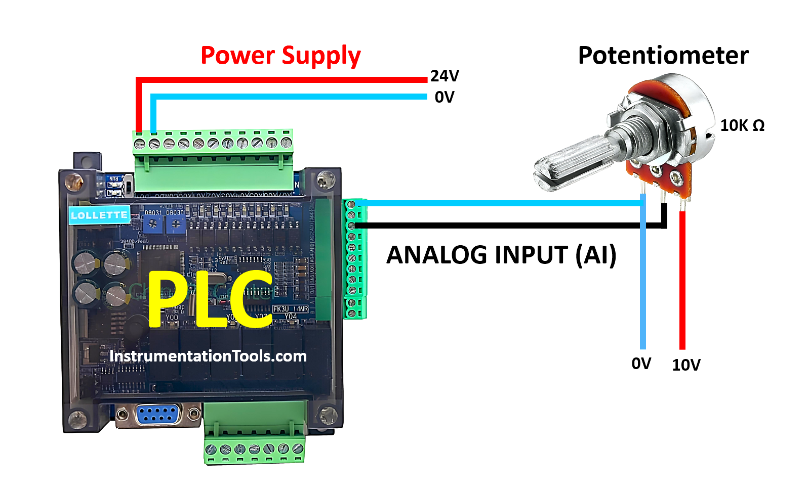
This article explains how to read analog input in the Mitsubishi PLC and display the value in the HMI software EasyBuilder Pro. In this system, the EasyBuilder Pro software will read data from the PLC’s word memory using Serial communication (RS232) in Online Simulation mode. This mode allows the HMI interface to run directly from a PC without requiring physical HMI hardware. The EasyBuilder Pro software will read 0-10 V input analog signal data that has been converted to 12-bit resolution (0-4095).
Required Devices
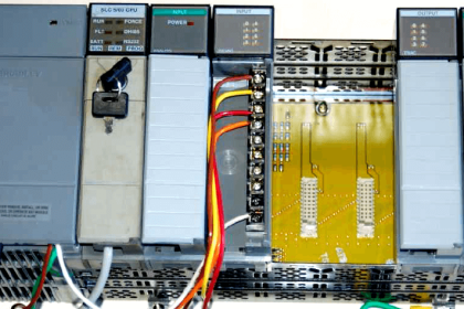
1. PLC FX3U-14MT
This PLC has 8 digital inputs, 6 transistor outputs, 4 analog inputs, 2 analog outputs, and 1 built-in RS-485 terminal contact. It operates on a 24V DC power supply and can only communicate using the Serial RS232 (DB9) port with a baud rate of 38.4 Kbps.
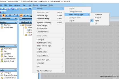
2. EasyBuilder Pro HMI Software
EasyBuilder Pro is HMI software from Weintek used to design interface displays and communication with PLCs. It is equipped with an online simulation feature without requiring physical HMI hardware and supports various industrial protocols such as Modbus Serial.
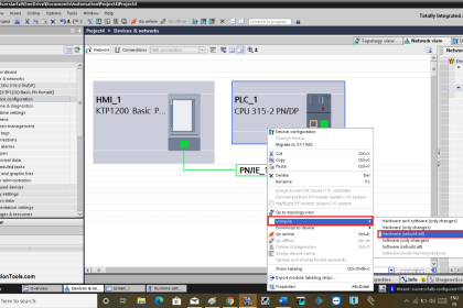
3. GX Works2 PLC Software
This is Mitsubishi’s official software for programming MELSEC series PLCs such as FX3U and FX5U. It supports ladder diagrams, real-time monitoring, and program debugging.
4. USB to Serial RS232 Converter
The USB to Serial RS232 converter cable functions as a communication interface adapter between modern computers (which typically only have USB ports) and legacy industrial devices such as PLCs, HMIs, sensors, or measuring instruments that use RS232 serial communication ports.
Read Mitsubishi PLC Analog Input and Display in HMI
In the video below, we tested the analog input data in the PLC using a potentiometer and the value displayed on the HMI.
Preparation:
- Connect a 24 V DC power supply to the PLC to power it up.
- Use a USB to Serial RS232 cable to connect the PLC to the computer.
Configuration Steps for Reading Analog Input on PLC FX3U-14MT
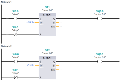
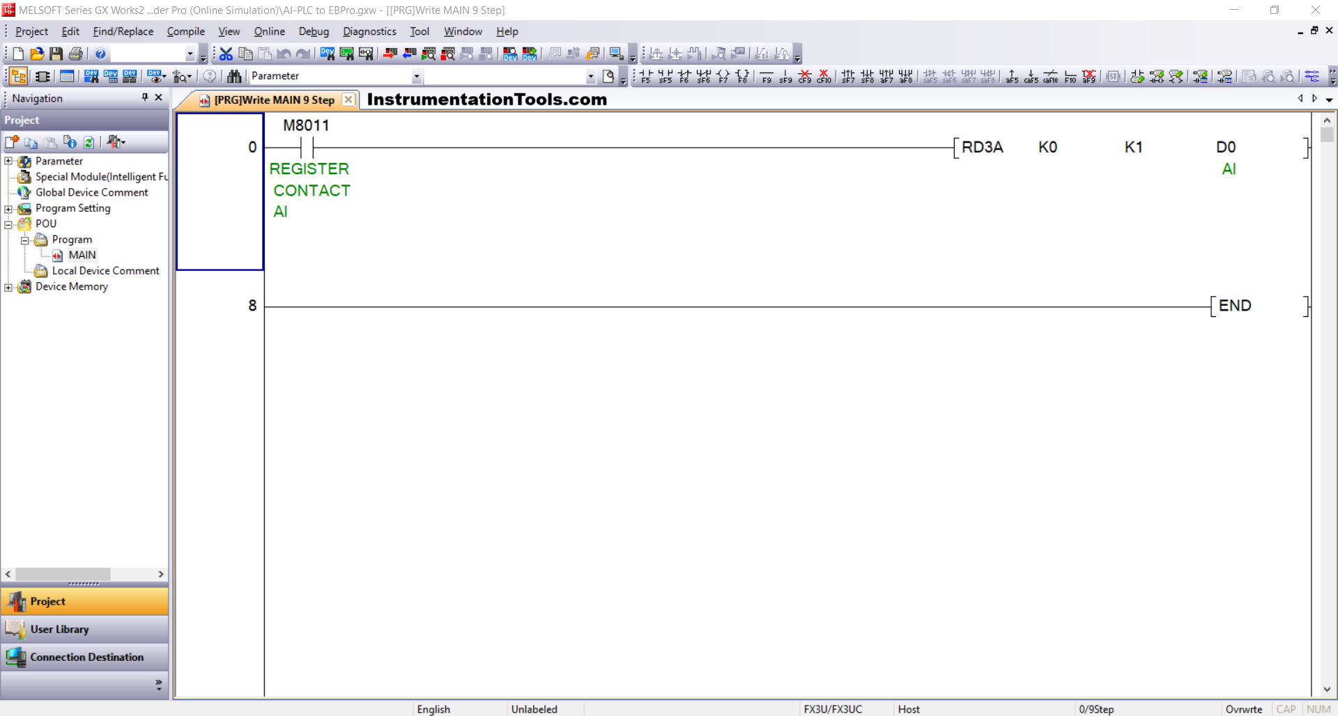
1. PLC Programming:
Create a program in GX Works2 software using the RD3A instruction, which is used to read analog input data.
- Module Configuration: 0/K0.
- Analog Input Address: 1/K1.
- Data Storage: The analog input value will be stored in word memory D0.
- Instruction Activation: Use the normally open contact from the memory bit REGISTER CONTACT AI (M8011) to trigger the instruction.
2. Device Connection Check
Make sure the USB to Serial RS232 adapter is connected and recognized by the computer:
Open Device Manager and check the COM port (e.g., COM5).
Ensure communication settings are configured as follows:
- Bit Rate: 38.4 Kbps
- Data Bits: 7Parity: Even
- Stop Bits: 1
3. Communication Settings in Software
Configure the connection in the programming software:
Navigate to: Connection Detection → Connection1
Set the following parameters:
- Interface: Serial USB (RS-232C)
- COM Port: COM5Transmission Speed: 38.4 Kbps
- Setup: Parity Even, Data Bits 7, Stop Bits 1
Run the Connection Test to confirm successful communication. A message will appear: “Successfully Connected with the FX3U/FX3UC CPU.”
4. Transfer the Program to PLC
Once the connection is confirmed:
- Go to Online → Write to PLC
- Select: Parameter + Program
- Click Execute to upload the program to the PLC memory.
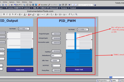
HMI Design and Simulation for Mitsubishi PLC Using EasyBuilder Pro
1. Create a New Project
Open EasyBuilder Pro. Select New, choose the HMI model (e.g., Weintek MT8071iE), and click OK to start a new project.
2. Add PLC Device
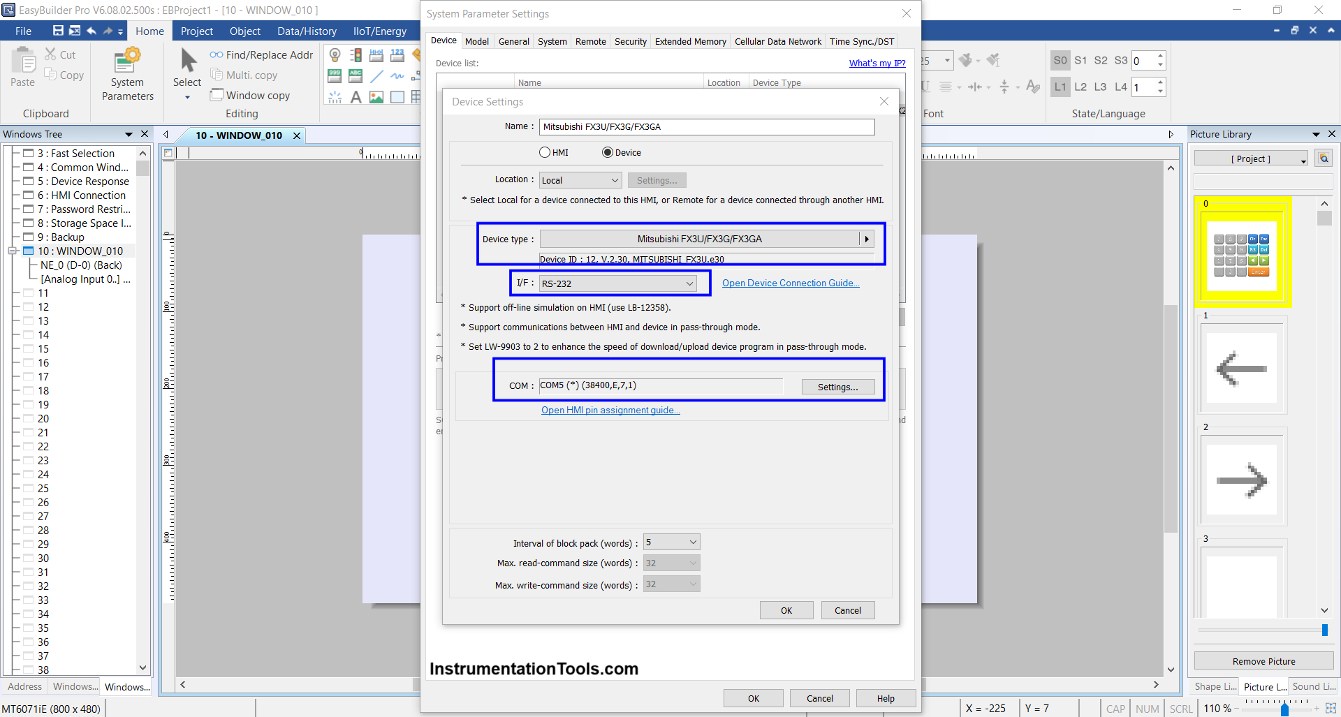
Open System Parameter and click New Device/Server.
Set the connection parameters as follows:
- Port: RS-232
- COM Port: COM5(*)(38400,E,7,1) — adjust according to your PLC connection
- Device Type: Mitsubishi FX3U/FX3G/FX3GA
Click OK to save the configuration.
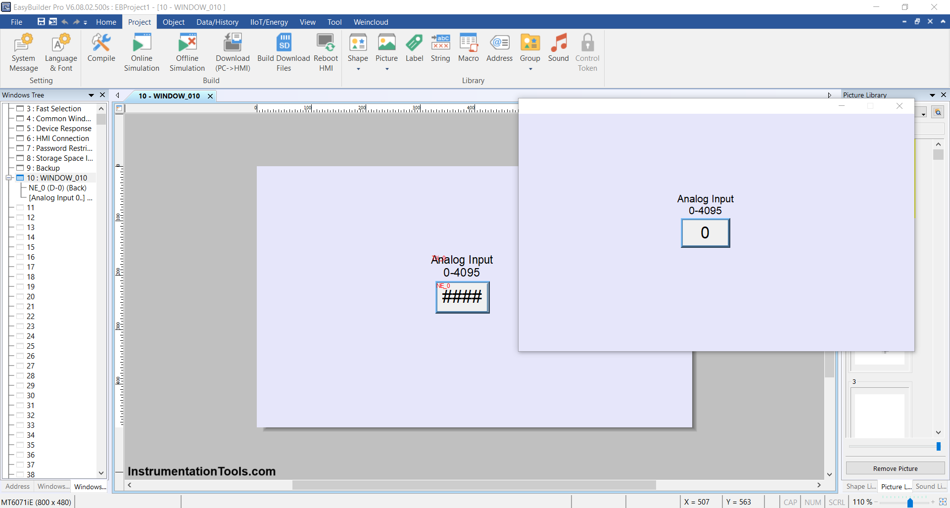
3. Design the HMI Interface
Insert a Numeric Object into the design area.
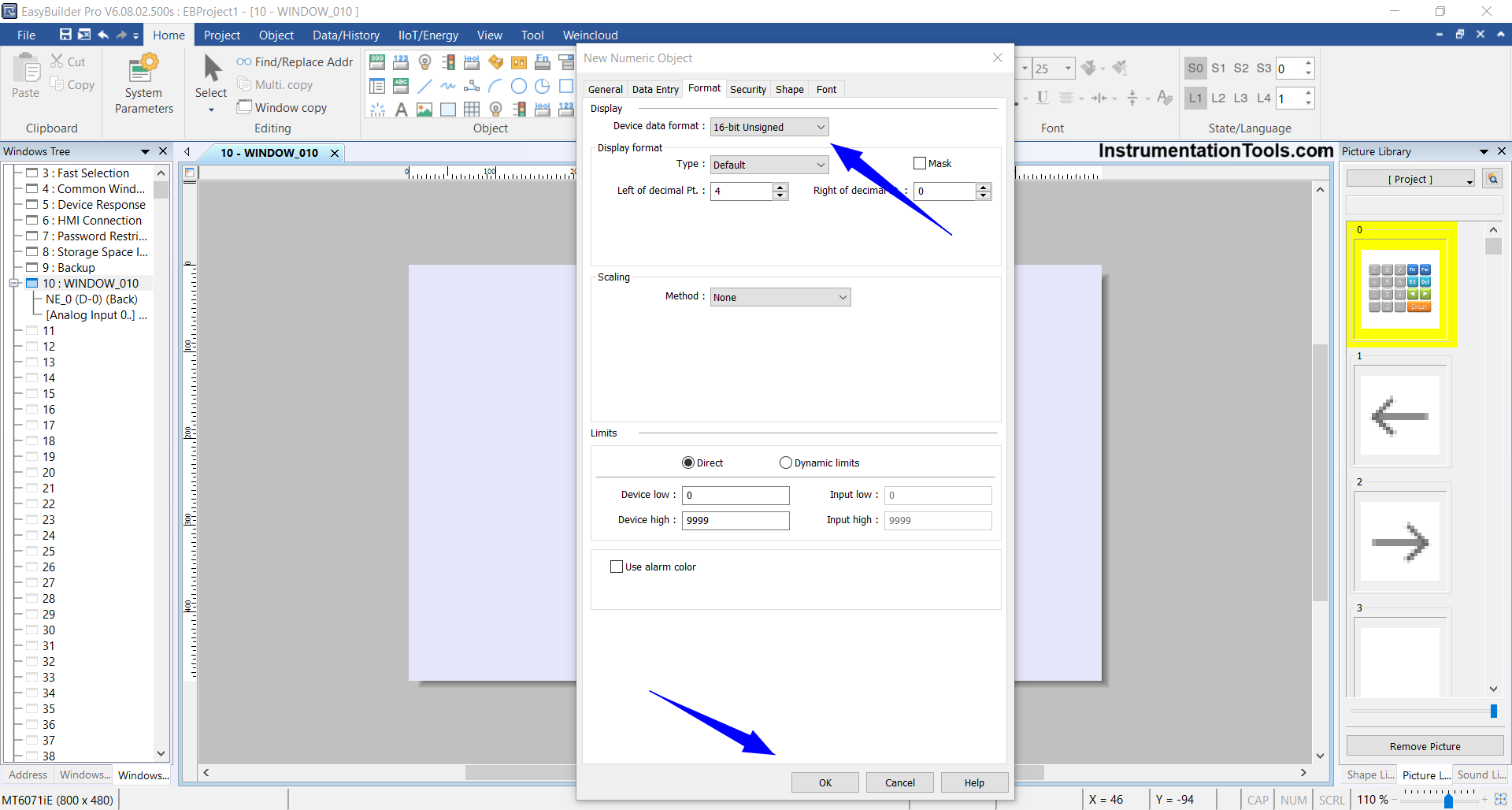
Configure the object settings:
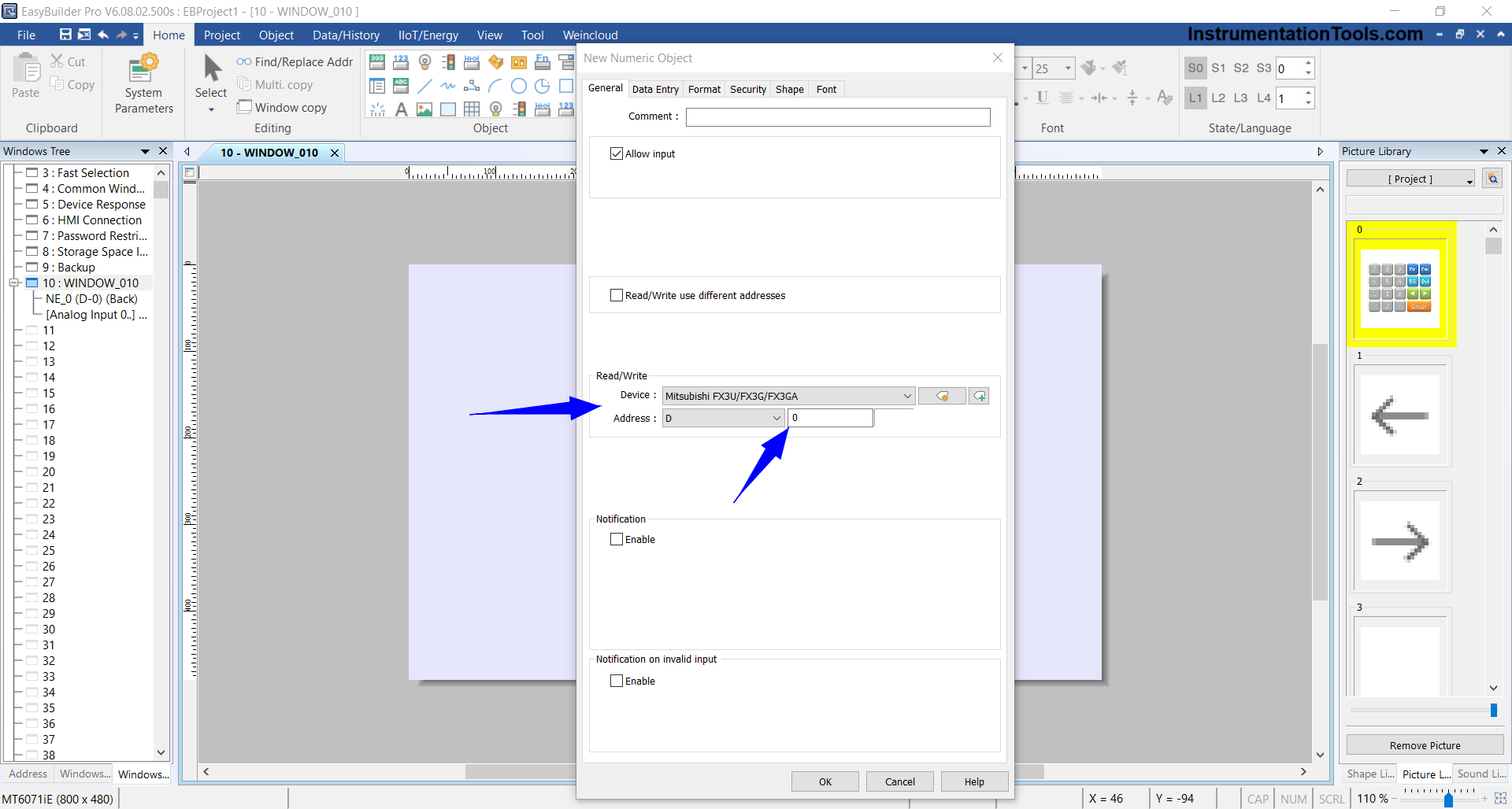
- Device: Mitsubishi FX3U/FX3G/FX3GA
- Address: D0 (corresponds to the analog input memory address in PLC)
- Data Format: 16-bit Unsigned
Click OK to place the object on the screen.
4. Run Online Simulation
Once the design is complete, start the simulation by selecting Project → Online Simulation.
5. Verify Connection
If the connection is successful, the simulation screen will appear and interact directly with the PLC.
*Important Note: If you see the message “Device Not Responding”, it indicates a failed connection.
Solution:
- Change the Device Type in System Parameter to FX0S/FX0N/FX1S/FX1N/FX2/FX3SA or another compatible type.
- This is because some units like the FX3U-14MT (Lollette, China version) have limited compatibility with the standard FX3U model in EasyBuilder Pro.
Read Next:
- Create an Application in HMI using Tia Portal
- Mitsubishi PLC + Weintek HMI: Analog Output
- About the SCADA and HMI Automation Systems
- PLC Programming for Industrial Oven Control
- Analog Voltage Control in PLC Using Weintek HMI