An example of ratio control at work is in a process whereby hydrocarbon gases (usually methane) are converted into hydrogen gas and carbon dioxide gas. This is known as the steam hydrocarbon reforming process, and it is one of the more popular ways of generating hydrogen gas for industrial use. The overall reaction for this process with methane gas (CH4) and steam (H2O) as the reactants is as follows (Note):
CH4 + 2H2O → 4H2 + CO2
Note : The conversion from hydrocarbon and steam to hydrogen and carbon dioxide is typically a two-stage process: the first (reforming) stage produces hydrogen gas and carbon monoxide, while a second (water-gas-shift) stage adds more steam to convert the carbon monoxide into carbon dioxide with more hydrogen liberated. Both reactions are endothermic, with the reforming reaction being more endothermic than the water-gas-shift reaction.
This is an endothermic chemical reaction, which means a net input of energy is required to make it happen. Typically, the hydrocarbon gas and steam are mixed together in a heated environment in the presence of a catalyst (to reduce the activation energy requirements of the reaction).
This usually takes the form of catalyst-packed metal tubes inside a gas-fired furnace. It is important to control the proportion of gas to steam flow into this process.
Too much hydrocarbon gas, and the result will be “coking” (solid hydrocarbon deposits) inside the heated tubes and on the surface of the catalyst beads, decreasing the efficiency of the process over time. T
oo much steam and the result is wasted energy as unreacted steam simply passes through the heater tubes, absorbing heat and carrying it away from the catalyst where it would otherwise do useful work.
One way to achieve the proper ratio of hydrocarbon gas to steam flow is to install a normal flow control loop on one of these two reactant feed lines, then use that process variable (flow) signal as a setpoint to a flow controller installed on the other reactant feed line.
This way, the second controller will maintain a proper balance of flow to proportionately match the flow rate of the other reactant.
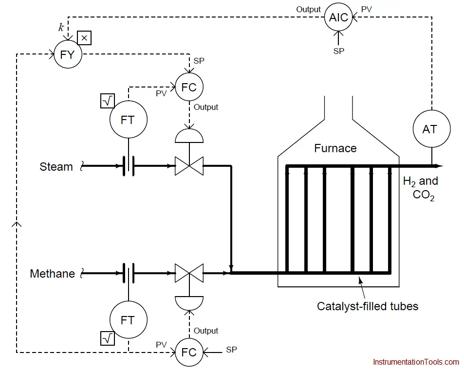
An example P&ID is shown here, where the methane gas flow rate establishes the setpoint for steam flow control:
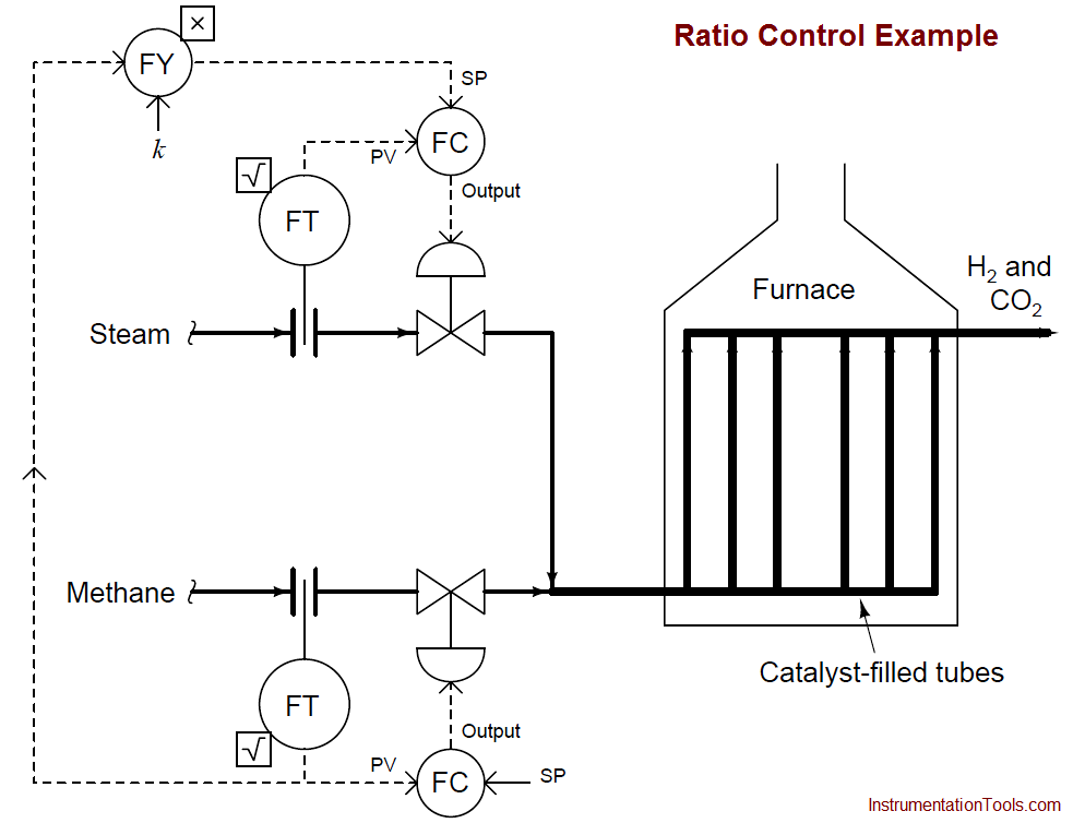
Note how the methane gas flow transmitter signal goes both to the methane flow controller and to a multiplying relay that multiplies this signal by a constant value (k) before passing it on to the steam flow controller as a setpoint. This k value sets the ratio of steam flow to methane flow.
Although this might appear to be a cascade control system at first glance, it is actually quite different. In a cascade system, the output of one controller becomes the setpoint for another.
Here in a ratio control system, the process variable of one controller becomes the setpoint for another, such that two process variables remain in constant proportion (ratio) to one another.
If the two flow transmitters are compensated to measure mass flow, the ideal value of k should be set such that two molecules of steam vapor (H2O) enter the reforming furnace for every one molecule of methane (CH4).
With a 2-to-1 molecular ratio of steam to methane (2 moles of steam per one mole of methane), this equates to a 9-to-4 mass flow ratio once the formula weights of steam and methane are calculated. Thus, if the methane and gas flowmeters are calibrated for equal mass flow ranges, the ideal value for k should be 9/4 , or 2.25.
Alternatively, the flow transmitter calibrations could be set in such a way that the ideal ratio is intrinsic to those transmitters’ ranges (i.e. the methane flow transmitter has 2.25 times the mass flow range of the steam flow transmitter), with k set to an ideal value of 1.
This way a 9:4 ratio of methane mass flow to steam mass flow will result in equal percentage output values from both flow transmitters. In practice, the value for k is set a bit higher than ideal, in order to ensure just a little excess steam to guard against coking inside the reaction heater tubes.
We could add another layer of sophistication to this ratio control system by installing a gas analyzer at the outlet of the reaction furnace designed to measure the composition of the product stream.
This analyzer’s signal could be used to adjust the value of k so the ratio of steam to methane would automatically vary to ensure optimum production quality even if the feedstock composition (i.e. percentage concentration of methane in the hydrocarbon gas input) changes:
As we saw before, pure methane feed requires a 9-to-4 steam-to-methane mass flow ratio for the desired reaction to be stoichiometrically balanced. This mass ratio, however, is not balanced for hydrocarbons other than methane.
Ethane (C2H6) processed in the same way requires a 12-to-5 steam-to-ethane mass flow ratio. Propane (C3H8) requires a 26-to-11 steam-to-propane mass flow ratio. If the hydrocarbon feed to the reforming furnace varies in composition, the steam flow ratio (k) must change accordingly for efficient reaction.