Examine these two pneumatic control loops (transmitter-controller-valve systems) for an industrial boiler, controlling both water level and steam pressure:
Pneumatic Control Loop
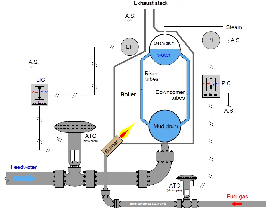
If the PIC setpoint is 225 PSI and the measured pressure begins to fall below that value, how should the PIC respond, and how will this response bring the steam pressure back up to setpoint?
If the pump supplying feedwater to the boiler begins to wear down over time, becoming less and less effective at providing water pressure to the level control valve, how do you suspect the LIC will respond over time as it works to maintain steam drum water level at setpoint?
Describe a situation where manual mode might be useful to either the boiler operator, or to an instrument technician tasked with maintaining either of these control loops.
Suppose the level transmitter’s calibration was 12 to 22 inches of water level while the level indicating controller’s calibration was 10 to 20 inches of water level. How many inches of water level would the LIC indicate when the actual steam drum water level was 17 inches?
Solution:
If pressure falls, PIC should increase fuel to burner.
As feedwater pump wears, LIC should open valve more.
The operator could use manual mode to gradually heat boiler during start-up, or to shut it down.
I’ll let you figure out what the LIC would indicate!
Share your answers & explanations.
Credits: Tony R. Kuphaldt
Read Next:
- Liquid Flow Control Loop
- Override Control Function
- Control Valve Sequence
- Setpoints and Alarms
- Commissioning Documents
