In this post, we will see the concept of scan time, and its types in a programmable logic controller (PLC).
A PLC consists of embedded functions like IO’s, communication, special designated functions etc. and a user-written program. Both these tasks need to be completed in a certain span of time.
Consider this concept as a satellite revolving around the earth. It always does this task in a certain span of time periodically, so that all the data are captured properly. The time should neither be such fast or less, that some data is missed; nor should be such slow or more, that time is wasted and information is not reached on time.
This theory is called scan time in PLC. It is nothing but the time which a PLC takes to execute all it’s software functions. A scan time is the core of any PLC system. Proper setting of it’s value defines the performance of the system.
There are applications where you need to set a lesser time, so that the executions work rapidly and you get the corresponding result very fast; like machine automation. Then there are applications where you can work with the default set time and execute the functions.
This can be any normal program or process automation, for best understanding. As there is no need to work fast unnecessary, there is thus no requirement to set a less time. All the functions will function properly without missing anything.
It depends entirely on the understanding of the PLC programmer; on how well he is able to define the time and make his work fulfil.
PLC Scan Cycle
Now that we have understood the basic concept, let us move ahead at the utmost function of scan time and how does it work.
A scan time has four main tasks – read input, execute the logic, write the output and work on the remaining interval with other low priority tasks.
Refer the below image for reference.
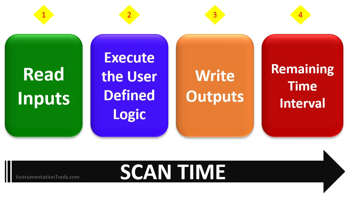
The physical values of the inputs are written in the input variables memory. After this, the user-written program is executed. Accordingly, the output values are updated in the output variables memory.
These output values are then updated on the physical outputs of PLC. In the remaining time, the PLC firmware carries out system processing and any other low priority tasks.
Types of Scan Time
Let us consider some general types of scan times used.
Cyclic Time
A cyclic time is assigned a fixed interval time. This means that the PLC will internally divide the maximum allotted time for each of the functions discussed.
This ensures that the PLC will try to complete all the tasks within the specified time. Compare this with the satellite example that we discussed earlier. It is same as this time.
This time is periodic in nature.
Freewheeling Time
A freewheeling time is not assigned a fixed interval time. This means that the PLC will execute the next task only on completion of the previous task.
This time is periodic in nature.
Event Task
An event task is executed on the trigger of any event. This trigger can be any memory variable.
On trigger, the tasks are executed in a single scan time, only once; in freewheel type mode (means, next step will continue after completion of previous step).
This time is conditional in nature.
External Event Task
This task is executed on the trigger of any external event. This trigger can be a digital input, any system function block output (means not from program, but configuration system block of any task) etc.
On trigger, the tasks are executed in a single scan time, only once; in freewheel type mode (means, next step will continue after completion of previous step).
This time is conditional in nature.
Important Notes on Scan Time
Let us consider some important notes while discussing the scan time in a PLC.
Selection of Scan Time
When you start writing a program, by default set time in the software works great anyways and don’t have to look into it. It can be between 10-20 ms.
Scan time is looked upon by two types of programs – one is fast and other is lengthy.
For a program requiring fast output from the logic, set a low scan time. But that shouldn’t be such low that it misses any task. Typical example can be 5 ms.
For a lengthy program of many rungs and sections, set a high scan time; so that all the tasks can be executed. It can be between 100-150 ms. Such types of lengthy programs are used where there are a large number of IO’s and cycles / processes.
Watchdog
Watchdog is an important term related with scan time. Basically, it is a user defined time to check whether the PLC is executing all the tasks within or around the specified scan time.
Suppose the scan time is 20 ms; then the watchdog timer can be 100 ms. If the program contains, for example, an endless loop, the watchdog causes the PLC to enter stop mode until the problem is fixed.
An endless loop can occur through any hardware malfunction or any wrong written program. PLC is forced to go to stop mode, to prevent any unnecessary damage to the system from the program. It can then be resumed only by power cycling the PLC or downloading the program again in the PLC.
Event Triggered Tasks
In case of event triggered tasks, a maximum rate of events per millisecond is defined.
It can be like, 7 events per millisecond. If the rate of trigger occurs at a very high frequency and goes above 7 events, then the PLC will go in stop mode.
Scanning
PLC program is always scanned from left to right, top to bottom in a single section.
So, suppose there are six sections written, then the first section numbered will be executed from left to right in a rung; then from top rung to the bottom rung and so on, till the sixth section. Then, the cycle repeats again.
Author: Viral Nagda
If you liked this article, then please subscribe to our YouTube Channel for Instrumentation, Electrical, PLC and SCADA video tutorials.
You can also follow us on Facebook and Twitter to receive daily updates.
Read Next:


Tnaks mr. viral for sharing very informative information in simple language.
Regds
Avinash Shinde