Inst ToolsInst ToolsInst Tools
  • Courses
  • Automation
    • PLC
    • Control System
    • Safety System
    • Communication
    • Fire & Gas System
  • Instrumentation
    • Design
    • Pressure
    • Temperature
    • Flow
    • Level
    • Vibration
    • Analyzer
    • Control Valve
    • Switch
    • Calibration
    • Erection & Commissioning
  • Interview
    • Instrumentation
    • Electrical
    • Electronics
    • Practical
  • Q&A
    • Instrumentation
    • Control System
    • Electrical
    • Electronics
    • Analog Electronics
    • Digital Electronics
    • Power Electronics
    • Microprocessor
  • Request
Search
  • Books
  • Software
  • Projects
  • Process
  • Tools
  • Basics
  • Formula
  • Power Plant
  • Root Cause Analysis
  • Electrical Basics
  • Animation
  • Standards
  • 4-20 mA Course
  • Siemens PLC Course
Reading: PLC Switch Actuation Status
Share
Notification Show More
Font ResizerAa
Inst ToolsInst Tools
Font ResizerAa
  • Courses
  • Design
  • PLC
  • Interview
  • Control System
Search
  • Courses
  • Automation
    • PLC
    • Control System
    • Safety System
    • Communication
    • Fire & Gas System
  • Instrumentation
    • Design
    • Pressure
    • Temperature
    • Flow
    • Level
    • Vibration
    • Analyzer
    • Control Valve
    • Switch
    • Calibration
    • Erection & Commissioning
  • Interview
    • Instrumentation
    • Electrical
    • Electronics
    • Practical
  • Q&A
    • Instrumentation
    • Control System
    • Electrical
    • Electronics
    • Analog Electronics
    • Digital Electronics
    • Power Electronics
    • Microprocessor
  • Request
Follow US
All rights reserved. Reproduction in whole or in part without written permission is prohibited.
Inst Tools > Blog > Practical Questions > PLC Switch Actuation Status

PLC Switch Actuation Status

Determine the necessary PLC switch actuation status (i.e. low versus high process stimulus) to turn the yellow lamp on.

Last updated: March 11, 2021 11:45 pm
Editorial Staff
Practical Questions
No Comments
Share
1 Min Read
SHARE

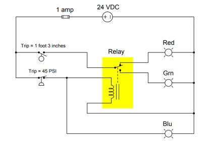
Suppose we have an Allen-Bradley MicroLogix 1000 controller connected to three process switches as shown in this illustration:

PLC Switch Actuation Status

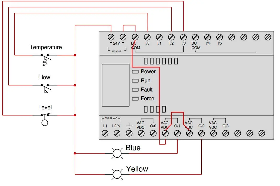
Determine the necessary switch actuation statuses (i.e. low versus high process stimulus) to turn the blue lamp on, given the following program running in the PLC:

Allen-Bradley MicroLogix 1000 controller ladder logic

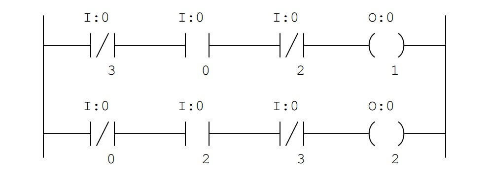
Next, determine the necessary switch actuation statuses (i.e. low versus high process stimulus) to turn the yellow lamp on, given the same PLC program.

Answer

High temperature and low flow and high level are required to energize the blue lamp.

Low temperature and high flow and high level are required to energize the yellow lamp.

Share Your Answer / Comments

Credits : by Tony R. Kuphaldt – under CC BY 1.0

Don't Miss Our Updates
Be the first to get exclusive content straight to your email.
We promise not to spam you. You can unsubscribe at any time.
Invalid email address
You've successfully subscribed !

Continue Reading

Identify Two Pressure Switches Logic
Thermocouple Measurement and Reference Junction Temperatures
Compressor Emergency Shutdown Root Cause Analysis
Draw a ladder logic circuit for the electric motor of an air compressor ?
Level Measuring Instruments Velocities of Propagation
Programmable Logic Controller (PLC) Questions and Answers – 11
Share This Article
Facebook Whatsapp Whatsapp LinkedIn Copy Link
Share
Leave a Comment

Leave a Reply Cancel reply

Your email address will not be published. Required fields are marked *

Stay Connected

128.3kFollowersLike
69.1kFollowersFollow
210kSubscribersSubscribe
38kFollowersFollow

Categories

Explore More

Programmable Logic Controller (PLC) Questions and Answers – 8
Calculate the Temperature of 4 Wire RTD
Differential Pressure Sensor with Pair of Strain Gauges
Calculate 0%, 50%, and 100% Calibration Points for ΔP transmitter
Displacer Level Transmitter 5-point Calibration
Identify High and Low Ports on Pneumatic DP Transmitter
Solenoid Valves Questions & Answers – 1
PT Loop Diagram Faults

Keep Learning

Determine Calibration Range of Pneumatic Pressure Transmitter

Determine Calibration Range of Pneumatic Pressure Transmitter

Identify which lamp in the following ladder-logic diagram

Identify High Flow Alarm and Low Flow Alarm?

Current-to-Pressure Transducer Calibration Table

Remote Seal Pressure Transmitter Temperature

Importance of Temperature in Remote Seal Pressure Transmitter

Pitot tube

Pitot Tube Flowmeter Calculations

A Question on Steam Drum Water Level Measurement

A Question on Steam Drum Water Level Measurement

Calculate the 0%, 50%, and 100% Calibration Points

Calculate the 0%, 50%, and 100% Calibration Points

DP Transmitter Wet Leg Compensating Impulse Line

Questions on DP Transmitter Wet Leg Compensating Impulse Line

Learn More

As-Interface Protocol Overview

AS-interface and DeviceNet Communication

Symbol of MOS Controlled Thyristor

MCT (MOS Controlled Thyristor) – Symbol, Working, Characteristics, Advantages

Inductive Time Constant

Inductive Time Constant

Triangle A-B-C- with Arc “A-C”

Instrument Tube Fitting Installation – Part 2

Hydrostatic level transmitter Formula

Hydrostatic Level Transmitter Questions

Digital Electronics Multiple Choice Questions

Introduction of Arithmetic Operation

Valve Diaphragm Actuator

Spring and Diaphragm Pneumatic Actuators

As-found and As-left Calibration

As-found and As-left Documentation during Calibration

Menu

  • About
  • Privacy Policy
  • Copyright

Quick Links

  • Learn PLC
  • Helping Hand
  • Part Time Job

YouTube Subscribe

Follow US
All rights reserved. Reproduction in whole or in part without written permission is prohibited.
Welcome Back!

Sign in to your account

Username or Email Address
Password

Lost your password?