Inst ToolsInst ToolsInst Tools
  • Ask
  • Courses
  • Videos
  • Q & A
    • Interview
      • Instrumentation
      • Electronics
      • Electrical
      • Practical Questions
    • MCQ
      • Instrumentation MCQ
      • Electrical MCQ
      • Electronics MCQ
      • Control Systems MCQ
      • Analog Electronics MCQ
      • Digital Electronics MCQ
      • Power Electronics MCQ
      • Microprocessor MCQ
      • Multiple Choice Questions
  • EE
    • Electronics
      • Electronics Q & A
      • Electronic Basics
      • Electronic Devices & Circuits
      • Electronics Animation
      • Digital Electronics
    • Electrical
      • Electrical Basics
      • Electrical Q & A
      • Power Electronics
      • Electrical Machines
      • Electrical Animation
      • Power Systems
      • Switchgear & Protection
      • Transmission & Distribution
  • Measure
    • Control Valves
    • Calibration
    • Temperature
    • Pressure
    • Flow
    • Level
    • Analyzers
    • Switches
    • Vibration
    • Solenoid Valve
  • Control
    • PLC Tutorials
    • Control Systems
    • Safety Instrumented System (SIS)
    • Communication
    • Fire & Gas System
  • More
    • Design
    • Tools
    • Animation
    • Basics
    • Formulas
    • Standards
    • TextBooks
    • Common
    • Software
    • Excel Tools
    • Erection & Commissioning
    • Process Fundamentals
    • Videos
    • Books
Search
All rights reserved. Reproduction in whole or in part without written permission is prohibited.
Reading: Program Flow Control Instructions in PLC Programming
Share
Notification Show More
Font ResizerAa
Inst ToolsInst Tools
Font ResizerAa
  • Courses
  • PLC Tutorials
  • Control Systems
Search
  • Ask
  • Courses
  • Videos
  • Q & A
    • Interview
    • MCQ
  • EE
    • Electronics
    • Electrical
  • Measure
    • Control Valves
    • Calibration
    • Temperature
    • Pressure
    • Flow
    • Level
    • Analyzers
    • Switches
    • Vibration
    • Solenoid Valve
  • Control
    • PLC Tutorials
    • Control Systems
    • Safety Instrumented System (SIS)
    • Communication
    • Fire & Gas System
  • More
    • Design
    • Tools
    • Animation
    • Basics
    • Formulas
    • Standards
    • TextBooks
    • Common
    • Software
    • Excel Tools
    • Erection & Commissioning
    • Process Fundamentals
    • Videos
    • Books
Follow US
All rights reserved. Reproduction in whole or in part without written permission is prohibited.
Inst Tools > Blog > PLC Tutorials > Program Flow Control Instructions in PLC Programming

Program Flow Control Instructions in PLC Programming

Last updated: March 4, 2021 3:11 pm
Editorial Staff
PLC Tutorials
No Comments
Share
7 Min Read
SHARE

Program Flow Control Instructions used to control the sequence in which your program is executed.

Contents
Program Flow Control InstructionsJump (JMP) and Label (LBL) InstructionsJMP InstructionLBL InstructionSBR InstructionMaster Control Reset (MCR)Temporary End (TND) InstructionSuspend (SUS) Instruction

Control instructions allow you to change the order in which the processor scans a ladder program.

Typically, these instructions are used to

  • minimize scan time,
  • create a more efficient program, and
  • troubleshoot a ladder program.

Program Flow Control Instructions
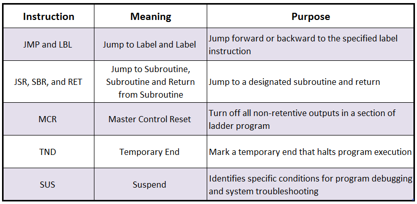
Program Flow Control Instructions in PLC Programming

Jump (JMP) and Label (LBL) Instructions

Labels have the format Q:NNN. NNN is a numeric value from 000-255.

Jumping forward to a label saves program scan time by omitting a program segment until needed.

Jumping backward lets the controller execute program segments repeatedly.

  • Be careful not to jump backward an excessive number of times.
  • The watchdog timer could time out and fault the controller.
  • Use a counter, timer, or the “program scan” register (system status register, word S:3, bits 0 to 7) to limit the amount of time you spend looping inside of JMP/LBL instructions.

JMP Instruction

The JMP instruction causes the controller to skip rungs. You can jump to the same label from one or more JMP instruction.

Also Read: PLC Example with JMP Instruction

LBL Instruction

This input instruction is the target of JMP instructions having the same label number.

You must program this instruction as the first instruction of a rung. This instruction has no control bits.

You can program multiple jumps to the same label by assigning the same label number to multiple JMP instructions. However, label numbers must be unique.

Note –

Do not jump (JMP) into an MCR zone. Instructions that are programmed within the MCR zone starting at the LBL instruction and ending at the ‘END MCR’ instruction are always evaluated as though the MCR zone is true, regardless of the true state of the “Start MCR” instruction.

SBR Instruction

If you use the SBR instruction, the SBR instruction must be the first instruction on the first rung in the program file that contains the subroutine.

Use a subroutine to store recurring sections of program logic that must be executed from several points within your application program.

A subroutine saves memory because you program it only once.

Update critical I/O within subroutines using immediate input and/or output instructions (IIM, IOM), especially if your application calls for nested or relatively long subroutines.

Otherwise, the controller does not update I/O until it reaches the end of the main program (after executing all subroutines).

Outputs controlled within a subroutine remain in their last state until the subroutine is executed again.

Master Control Reset (MCR)

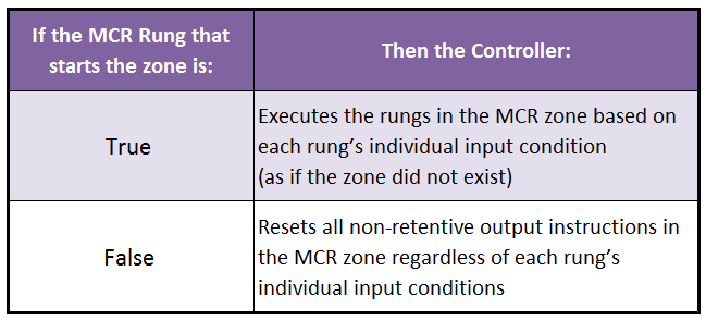
MCR zones let you enable or inhibit segments of your program, such as for recipe applications.

When you program MCR instructions, note that:

  • You must end the zone with an unconditional MCR instruction.
  • You cannot nest one MCR zone within another.
  • Do not jump into an MCR zone. If the zone is false, jumping into it activates the zone.
  • Always place the MCR instruction as the last instruction in a rung.
Master Control Reset (MCR)  Symbol
rslogix mcr instruction

Use MCR instructions in pairs to create program zones that turn off all the non-retentive outputs in the zone.

  • Rungs within the MCR zone are still scanned, but scan time is reduced due to the false state of non-retentive outputs.

The MCR instruction is not a substitute for a hard-wired master control relay that provides emergency stop capability.

  • You should still install a hard–wired master control relay to provide emergency I/O power shutdown.

Also Read: PLC Example with MCR Zone

Do not jump (JMP) into an MCR zone.

  • Instructions that are programmed within the MCR zone starting at the LBL instruction and ending at the ‘END MCR’ instruction are always evaluated as though the MCR zone is true, regardless of the true state of the “Start MCR” instruction. If the zone is false, jumping into it activates the zone from the LBL to the end of the zone.

If you start instructions such as timers or counters in an MCR zone, instruction operation ceases when the zone is disabled.

  • Re-program critical operations outside the zone if necessary.

The TOF timer activates when placed inside of a false MCR zone.

Temporary End (TND) Instruction

The TND instruction, when its rung is true:

  • Stops the processor from scanning the rest of the program file
  • Updates the I/O, and
  • Resumes scanning at rung 0 of the main program (file 2)

If this instruction’s rung is false, the processor continues the scan until the next TND instruction or the END statement.

Use this instruction to progressively debug a program, or conditionally omit the balance of your current program file or subroutines

Suspend (SUS) Instruction

When the SUS instruction is executed, it causes the processor to enter the Suspend Idle mode and stores the Suspend ID in word 7 (S:7) of the status file.

Suspend (SUS) Instruction in PLC

All outputs are de-energized.

Use the SUS instruction to trap and identify specific conditions for program debugging and system troubleshooting.

If you liked this article, then please subscribe to our YouTube Channel for PLC and SCADA video tutorials.

You can also follow us on Facebook and Twitter to receive daily updates.

Read Next:

Closed-Loop Control using PLC

PLC Ladder Logics Instructions

Waste Water Control System

PID Controller Selection Logic

What is Direct Digital Control?
Don't Miss Our Updates
Be the first to get exclusive content straight to your email.
We promise not to spam you. You can unsubscribe at any time.
Invalid email address
You've successfully subscribed !
Principle of Operation of PLC
PLC Program for Entry and Exit Control of Car Parking
Positive and Negative Edges using Statement List Language
Comparison Instructions in PLC Programming
Write a PLC Program for Selector Machine using Structured Text
Share This Article
Facebook Whatsapp Whatsapp LinkedIn Copy Link
Share
Leave a Comment

Leave a Reply Cancel reply

Your email address will not be published. Required fields are marked *

Stay Connected

128.3kFollowersLike
69.1kFollowersFollow
208kSubscribersSubscribe
38kFollowersFollow

Categories

Recent Comments

  • Kamli on Top Free PLC Software
  • Guifty Shimica on Top Non-PLC Certification Courses for Automation Professionals
  • Guifty Shimica on Top Non-PLC Certification Courses for Automation Professionals
  • MIHARITSOA Aina Sitraka on Top Non-PLC Certification Courses for Automation Professionals

Related Articles

PLC Scan Time

PLC Scan Time

PLC Battery

Everything You Need to Know About PLC Battery

Grounding Electronic Equipment

Importance of Grounding Electronic Equipment

FIFO and LIFO Sequences in PLC

What are FIFO and LIFO Sequences in PLC?

CPU Communication Ports in Siemens PLC

Types of CPU Communication Ports in Siemens PLC

Rewire Tool

What is Rewire Tool in Simatic Manager?

Difference Between Static and Temp Memory in Siemens TIA Portal

Difference Between Static and Temp Memory in Siemens PLC TIA Portal

Ladder Logic of Motor Forward and Reverse

PLC Programming Example for Motor Forward and Reverse Control

More Articles

Digital Electronics Multiple Choice Questions

Shift Registers Objective Questions

valve plug and seat damage

Control Valve Erosion Problems

Electropneumatic Valve Positioner Working Principle

Electro Pneumatic Valve Positioner Schematic & Principle

Pollution Monitoring Instruments Questions and Answers

Sulphur Di-oxide Monitoring Questions & Answers

Impulse Line Pressure Testing Procedure

Impulse Line Pressure Testing Procedure

Thermowell Immersion Length

Thermowell Insertion and Immersion Length

Ultrasonic level measurement

Ultrasonic Level Measurement

Hot Well Level Control System in Condensing Turbine

Hot Well Level Control System in Condensing Turbine

Follow US
All rights reserved. Reproduction in whole or in part without written permission is prohibited.
Welcome Back!

Sign in to your account

Username or Email Address
Password

Lost your password?