Inst ToolsInst ToolsInst Tools
  • Courses
  • Automation
    • PLC
    • Control System
    • Safety System
    • Communication
    • Fire & Gas System
  • Instrumentation
    • Design
    • Pressure
    • Temperature
    • Flow
    • Level
    • Vibration
    • Analyzer
    • Control Valve
    • Switch
    • Calibration
    • Erection & Commissioning
  • Interview
    • Instrumentation
    • Electrical
    • Electronics
    • Practical
  • Q&A
    • Instrumentation
    • Control System
    • Electrical
    • Electronics
    • Analog Electronics
    • Digital Electronics
    • Power Electronics
    • Microprocessor
  • Request
Search
  • Books
  • Software
  • Projects
  • Process
  • Tools
  • Basics
  • Formula
  • Power Plant
  • Root Cause Analysis
  • Electrical Basics
  • Animation
  • Standards
  • 4-20 mA Course
  • Siemens PLC Course
Reading: Process Variable Damping of Transmitter
Share
Font ResizerAa
Inst ToolsInst Tools
Font ResizerAa
  • Courses
  • Design
  • PLC
  • Interview
  • Control System
Search
  • Courses
  • Automation
    • PLC
    • Control System
    • Safety System
    • Communication
    • Fire & Gas System
  • Instrumentation
    • Design
    • Pressure
    • Temperature
    • Flow
    • Level
    • Vibration
    • Analyzer
    • Control Valve
    • Switch
    • Calibration
    • Erection & Commissioning
  • Interview
    • Instrumentation
    • Electrical
    • Electronics
    • Practical
  • Q&A
    • Instrumentation
    • Control System
    • Electrical
    • Electronics
    • Analog Electronics
    • Digital Electronics
    • Power Electronics
    • Microprocessor
  • Request
Follow US
All rights reserved. Reproduction in whole or in part without written permission is prohibited.
Inst Tools > Blog > Instrumentation Design > Process Variable Damping of Transmitter

Process Variable Damping of Transmitter

Last updated: August 14, 2019 4:38 pm
Editorial Staff
Instrumentation Design
No Comments
Share
2 Min Read
SHARE

Process Variable Damping

The PV Damping command of a transmitter changes the response time of the transmitter to smooth variations in output readings caused by rapid changes in input. Determine the appropriate damping setting based on the necessary response time, signal stability, and other requirements of the loop dynamics of the system.

The value chosen for damping affects the response time of the transmitter. When set to zero (or disabled), the damping function is off and the transmitter output reacts to changes in input as quickly as the intermittent sensor algorithm allows. Increasing the damping value increases the transmitter response time.

With damping enabled (say set to 5 sec ) , if the temperature change is within 0.2% of the sensor limits, the transmitter measures the change in input every 500 milliseconds and outputs values according to the following relationship:

Process Variable Damping Formula

Where,

P =previous damped value
N =new sensor value
T = damping time constant
U = constant

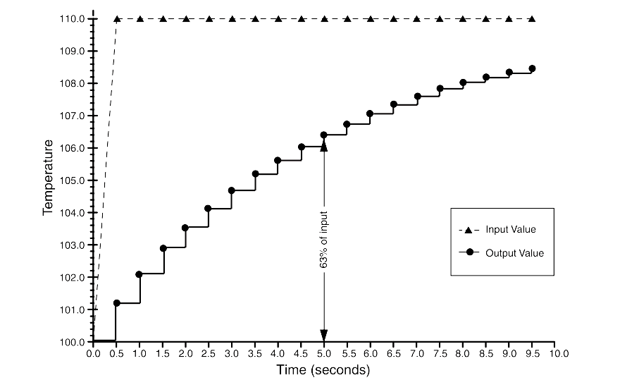
At the value to which the damping time constant is set, the transmitter output is at 63% of the input change and it continues to approach the input according to the damping equation above.

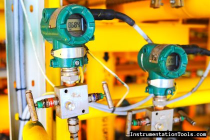
For example consider a temperature transmitter, as illustrated in Below Figure, if the temperature undergoes a step change—within 0.2% of the sensor limits—from 100 degrees to 110 degrees, and the damping is set to 5.0 seconds, the transmitter calculates and reports a new reading every 500 milliseconds using the damping equation.

At 5.0 seconds, the transmitter outputs 106.3 degrees, or 63% of the input change, and the output continues to approach the input curve according to the equation above.

Process Variable Damping Graph

Reference : Rosemount Temperature Manual

Don't Miss Our Updates
Be the first to get exclusive content straight to your email.
We promise not to spam you. You can unsubscribe at any time.
Invalid email address
You've successfully subscribed !

Continue Reading

Ferrules and Cross Ferruling
Why is Orifice Beta in between 0.3 to 0.7?
What to Choose RTD or Thermocouple ?
Basic Terms used in SIL Verification
History of 3-15 psi, 10-50 mA, and 4-20 mA signals
Process Control & Safety Systems Logics Implementing Cycle
Share This Article
Facebook Whatsapp Whatsapp LinkedIn Copy Link
Share
Leave a Comment

Leave a Reply Cancel reply

Your email address will not be published. Required fields are marked *

Stay Connected

128.3kFollowersLike
69.1kFollowersFollow
210kSubscribersSubscribe
38kFollowersFollow

Categories

Explore More

Motor Control Circuit Wiring
Instrument Cables Sheath Material
What is Instrument DataSheet ?
All About Vortex Flow Meters
How to Select the Right Panel Enclosure for Your Application?
Detail Design Engineering Competency Aspects
Flow Instruments – Selection, Principle & Application
Major issues for Sensors Selection

Keep Learning

Location of Measurement Displays

Location of Measurement Displays

How to choose between PLC and DCS Systems

How to choose between PLC and DCS Systems ?

Control systems in industrial projects

Interactions With Process Control Systems Philosophy

Twisted Pair Cable Noise Supression

Why We use Shielded Cable and Twisted Pair Cables ?

Instrument Numbering Philosophy

Instrument Numbering Philosophy

Controller Output Current Loop

DCS Controllers to Output Current Loops

Pressure Regulators vs Pressure Control Valves

Pressure Control Valves vs Pressure Regulators

30 Concerns for Control System Philosophy (Industrial Automation)

30 Concerns for Process Control Systems Philosophy

Learn More

Comparison of Accuracy and Precision

Difference between Accuracy and Precision

Guided-wave Radar Level Measurement Animation

bourdon-tube-pressure-gauge-working-animation

Working Principle of Pressure Gauge

High and Low Ports on Pneumatic DP Transmitter

Identify High and Low Ports on Pneumatic DP Transmitter

Electrical Simulator

Free Electrical Circuits Simulator Download

Mechanical Vibration Switch

Vibration Switch Working Principle

PLC program for Sorting System by Size Example

PLC Based Product Sorting Machine System – Lift Control

Power Electronics Objective Questions

Thyristor MCQ

Menu

  • About
  • Privacy Policy
  • Copyright

Quick Links

  • Learn PLC
  • Helping Hand
  • Part Time Job

YouTube Subscribe

Follow US
All rights reserved. Reproduction in whole or in part without written permission is prohibited.
Welcome Back!

Sign in to your account

Username or Email Address
Password

Lost your password?