Inst ToolsInst ToolsInst Tools
  • Courses
  • Automation
    • PLC
    • Control System
    • Safety System
    • Communication
    • Fire & Gas System
  • Instrumentation
    • Design
    • Pressure
    • Temperature
    • Flow
    • Level
    • Vibration
    • Analyzer
    • Control Valve
    • Switch
    • Calibration
    • Erection & Commissioning
  • Interview
    • Instrumentation
    • Electrical
    • Electronics
    • Practical
  • Q&A
    • Instrumentation
    • Control System
    • Electrical
    • Electronics
    • Analog Electronics
    • Digital Electronics
    • Power Electronics
    • Microprocessor
  • Request
Search
  • Books
  • Software
  • Projects
  • Process
  • Tools
  • Basics
  • Formula
  • Power Plant
  • Root Cause Analysis
  • Electrical Basics
  • Animation
  • Standards
  • 4-20 mA Course
  • Siemens PLC Course
Reading: Problem in Water Level Control System
Share
Font ResizerAa
Inst ToolsInst Tools
Font ResizerAa
  • Courses
  • Design
  • PLC
  • Interview
  • Control System
Search
  • Courses
  • Automation
    • PLC
    • Control System
    • Safety System
    • Communication
    • Fire & Gas System
  • Instrumentation
    • Design
    • Pressure
    • Temperature
    • Flow
    • Level
    • Vibration
    • Analyzer
    • Control Valve
    • Switch
    • Calibration
    • Erection & Commissioning
  • Interview
    • Instrumentation
    • Electrical
    • Electronics
    • Practical
  • Q&A
    • Instrumentation
    • Control System
    • Electrical
    • Electronics
    • Analog Electronics
    • Digital Electronics
    • Power Electronics
    • Microprocessor
  • Request
Follow US
All rights reserved. Reproduction in whole or in part without written permission is prohibited.
Inst Tools > Blog > Control Systems > Problem in Water Level Control System

Problem in Water Level Control System

Last updated: February 25, 2020 7:46 am
Editorial Staff
Control Systems
No Comments
Share
2 Min Read
SHARE

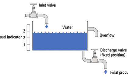
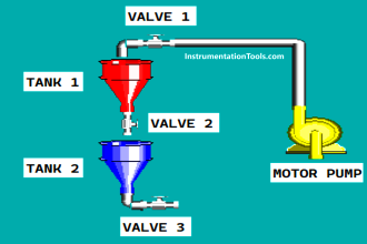
This water level control system (for a municipal water supply operation) is supposed to maintain constant water level in the filter and in the clearwell. Unfortunately, it has a problem. Operators call you urgently to determine why the clearwell is completely empty:

Water Level Control System

Problem in Water Level Control System

Your first step is to ask the operator if they have actually inspected the clearwell to verify that it is empty. They have, and it is. They also point to the display for level controller LIC-30 and show you that it reads 0% level.

Identify the likelihood of each specified fault for this water filtration system. Consider each fault one at a time (i.e. no coincidental faults), determining whether or not each fault could independently account for all measurements and symptoms in this system.

Also identify the below mentioned faults are possible or impossible?

  • Transmitter FT-21 failed with low output
  • Transmitter FT-21 failed with high output
  • Transmitter LT-25 failed with low output
  • Transmitter LT-25 failed with high output
  • Transmitter FT-28 failed with low output
  • Transmitter FT-28 failed with high output
  • Transmitter LT-30 failed with low output
  • Transmitter LT-30 failed with high output
  • Effluent pump turned off

Finally, identify the next diagnostic test or measurement you would make on this system. Explain how the result(s) of this next test or measurement help further identify the location and/or nature of the fault.

Join the discussion!. Share your answers with us through below comments section.

Read Next:

  • Instrument Maintenance
  • Water Level Control Logic
  • Turbine Control System
  • Feedforward Control Action
  • Terms in Water Supply System

Credits: Tony R. Kuphaldt

Don't Miss Our Updates
Be the first to get exclusive content straight to your email.
We promise not to spam you. You can unsubscribe at any time.
Invalid email address
You've successfully subscribed !

Continue Reading

Loop Check of 4-20mA or HART Transmitters
What is Anti Surge System?
What is Loop Checking?
Hardware Troubleshooting Steps for PLC Automation Systems
I&C Engineer Roles & Responsibilities – Instrumentation Design
Steady-State Process Gain
Share This Article
Facebook Whatsapp Whatsapp LinkedIn Copy Link
Share
Leave a Comment

Leave a Reply Cancel reply

Your email address will not be published. Required fields are marked *

Stay Connected

128.3kFollowersLike
69.1kFollowersFollow
210kSubscribersSubscribe
38kFollowersFollow

Categories

Explore More

How to Download PlantPAx Library?
What is Ground, and importance of a Grounding System?
Distributed Control System Interview Questions
On/off Control Theory
What is Timeout in Communication Protocols?
Types of SCADA System Architecture
System Architecture and Process Control Systems Philosophy
Standard Colors in PLC Automation Systems

Keep Learning

Inspection and Testing of Fiber Optic Cable

Inspection and Testing of Fiber Optic Cable

Smart HART Transmitter

Analysis of HART communicator and Smart HART Transmitter

Industrial Automation Systems

Remote Functions in Industrial Control Systems (ICS)

How Engineers Effectively do Problem-solve and Troubleshoot

How Engineers Effectively do Problem-solve and Troubleshoot?

On-Off Controller example

ON-OFF Controller Principle

Analog Instruments

Explaining Various Types of Analog Instruments

Enterprise Resource Planning in Industrial Automation

What is ERP in Industrial Automation? – Enterprise Resource Planning

2-wire loop-powered transmitter

Loop Controller HART Signal Noise

Learn More

Mass Spectrometer Questions and Answers

Inductively Coupled Plasma Mass Spectrometer

Biomedical Instrumentation Questions and Answers

Biomedical Instrumentation Questions and Answers

Why Do We Need to Connect Transformers in Parallel

Why Do We Need to Connect Transformers in Parallel?

PID control block located in fieldbus transmitter

Foundation Fieldbus Device addressing

Database for each safety module

Global Acknowledgment Instruction in Safety PLC

DP-Transmitter-with-two-seals

DP Transmitter with Two Seals applications

Supervisory Control

Supervisory Control

Connect PLC with SCADA System via OPC UA

How to Connect PLC with SCADA System via OPC UA?

Menu

  • About
  • Privacy Policy
  • Copyright

Quick Links

  • Learn PLC
  • Helping Hand
  • Part Time Job

YouTube Subscribe

Follow US
All rights reserved. Reproduction in whole or in part without written permission is prohibited.
Welcome Back!

Sign in to your account

Username or Email Address
Password

Lost your password?