Inst ToolsInst ToolsInst Tools
  • Ask
  • Courses
  • Videos
  • Q & A
    • Interview
      • Instrumentation
      • Electronics
      • Electrical
      • Practical Questions
    • MCQ
      • Instrumentation MCQ
      • Electrical MCQ
      • Electronics MCQ
      • Control Systems MCQ
      • Analog Electronics MCQ
      • Digital Electronics MCQ
      • Power Electronics MCQ
      • Microprocessor MCQ
      • Multiple Choice Questions
  • EE
    • Electronics
      • Electronics Q & A
      • Electronic Basics
      • Electronic Devices & Circuits
      • Electronics Animation
      • Digital Electronics
    • Electrical
      • Electrical Basics
      • Electrical Q & A
      • Power Electronics
      • Electrical Machines
      • Electrical Animation
      • Power Systems
      • Switchgear & Protection
      • Transmission & Distribution
  • Measure
    • Control Valves
    • Calibration
    • Temperature
    • Pressure
    • Flow
    • Level
    • Analyzers
    • Switches
    • Vibration
    • Solenoid Valve
  • Control
    • PLC Tutorials
    • Control Systems
    • Safety Instrumented System (SIS)
    • Communication
    • Fire & Gas System
  • More
    • Design
    • Tools
    • Animation
    • Basics
    • Formulas
    • Standards
    • TextBooks
    • Common
    • Software
    • Excel Tools
    • Erection & Commissioning
    • Process Fundamentals
    • Videos
    • Books
Search
All rights reserved. Reproduction in whole or in part without written permission is prohibited.
Reading: Problem on Pressure and Level Control Loops
Share
Notification Show More
Font ResizerAa
Inst ToolsInst Tools
Font ResizerAa
  • Courses
  • PLC Tutorials
  • Control Systems
Search
  • Ask
  • Courses
  • Videos
  • Q & A
    • Interview
    • MCQ
  • EE
    • Electronics
    • Electrical
  • Measure
    • Control Valves
    • Calibration
    • Temperature
    • Pressure
    • Flow
    • Level
    • Analyzers
    • Switches
    • Vibration
    • Solenoid Valve
  • Control
    • PLC Tutorials
    • Control Systems
    • Safety Instrumented System (SIS)
    • Communication
    • Fire & Gas System
  • More
    • Design
    • Tools
    • Animation
    • Basics
    • Formulas
    • Standards
    • TextBooks
    • Common
    • Software
    • Excel Tools
    • Erection & Commissioning
    • Process Fundamentals
    • Videos
    • Books
Follow US
All rights reserved. Reproduction in whole or in part without written permission is prohibited.
Inst Tools > Blog > Control Systems > Problem on Pressure and Level Control Loops

Problem on Pressure and Level Control Loops

Last updated: October 13, 2020 9:54 am
Editorial Staff
Control Systems
1 Comment
Share
3 Min Read
SHARE

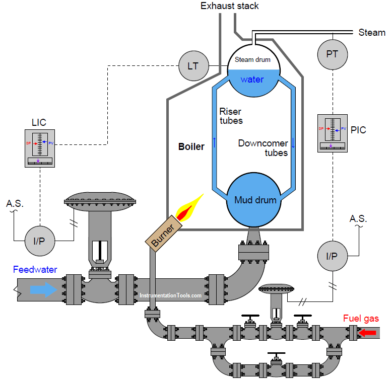
Examine these pressure and level control loops (transmitter-controller-valve systems) for an industrial boiler, controlling both water level and steam pressure:

Contents
Pressure and Level Control LoopsAnswer:Questions for you

Pressure and Level Control Loops

Pressure and Level Control Loop

If the PIC setpoint is 225 PSI and the measured steam pressure begins to rise above that value, how should the PIC respond, and how will this response bring the steam pressure back down to setpoint?

Describe a situation where the block and bypass hand valves installed on the fuel gas line might ever be used, either by operations or by maintenance personnel.

If the I/P transducer on the level control loop suddenly fell out of calibration in such a way that it output a pneumatic signal that was too low, how would this affect the control of water level in the steam drum?

Answer:

If steam pressure begins to fall below setpoint, the PIC should send a decreasing signal to the fuel gas valve, causing the burner to output less heat and thereby lowering the steam pressure to setpoint again. If well-tuned, a loop controller will drive its output signal to whatever value is necessary to achieve PV = SP.

The manual block and bypass valves are useful for taking the fuel control valve out of service while the boiler is still running. This allows technicians to stroke-test and even replace the control valve without shutting down the boiler. I will let you describe and explain the sequence of valve motions necessary to take a working control valve out of service. (use comments section to share your way of doing it.)

A falsely-low pressure signal coming from the I/P might cause the actual water level to drop if the change was sudden, but the LIC will eventually compensate for this change by adjusting its output signal value until the control valve is at the correct position again.

Questions for you

Explain what would happen to this process if the air supply to the feedwater valve’s I/P transducer failed.

Explain what would happen to this process if the air supply to the fuel valve’s I/P transducer failed.

Explain how both control loops will respond to a sudden increase in steam demand.

Share Your Answers with us through comments.

Read Next:

  • Pressure Loop Wiring
  • Voltage Drops at Flow Rates
  • Pneumatic Control Loop
  • Loop Controller HART Noise
  • Calibrator 4-20 mA Signal

Credits: Tony R. Kuphaldt
Don't Miss Our Updates
Be the first to get exclusive content straight to your email.
We promise not to spam you. You can unsubscribe at any time.
Invalid email address
You've successfully subscribed !
Five Levels in Industrial Automation
ICS System Design Considerations
Instrumentation and Control Project Packages – Detail Engineering
Control Panels Material Take-Off (MTO) – Engineering Project
PLC vs PAC – Understanding the Key Differences and Similarities
Share This Article
Facebook Whatsapp Whatsapp LinkedIn Copy Link
Share
1 Comment
  • Chinmay Karekar says:
    October 13, 2020 at 9:37 pm

    Answer: I am trying to giving an answer just with a basic knowledge of Control loops

    1) Assuming that Feedwater valve is ATO, if air supply fails, then feedwater shut off, hence water drum level start decreasing and at the same time PIC loop maintains the Fuel supply such that Steam demand fulfills. but due to shortage of water in drum or tubes, the burner may rupture the tubes if fuel supply not shut.

    2) Assuming that Fuel Supply valve is ATO, if air supply fails, then Fuel Supply shut off and burner also stops. Hence water doesn’t get converted into steam, and steam demand goes on increasing.

    3)If there is sudden increase in Steam demand, then PIC Loop open more Fuel Supply Valve to generate more steam, and results to decrease in water level, hence at the same time LIC Loop will open more Feedwater valve to compensate for water level demand.

    Reply

Leave a Reply Cancel reply

Your email address will not be published. Required fields are marked *

Stay Connected

128.3kFollowersLike
69.1kFollowersFollow
208kSubscribersSubscribe
38kFollowersFollow

Categories

Recent Comments

  • MIHARITSOA Aina Sitraka on Top Non-PLC Certification Courses for Automation Professionals
  • Vaishnavi on Free Instrumentation Course for Trainee Engineers
  • anuj kapoor on DCS Program to Maintain Draft in Furnace
  • anuj kapoor on IoT based Smart Boiler Control System with Cloud PLC and SCADA

Related Articles

Automation in Mining Industry

Industrial Automation in the Mining Industry

Different Control Modes of Air Handling Unit (AHU)

Control Modes of Air Handling Unit (AHU) – HVAC Basics

Hot Well Level Control System in Condensing Turbine

Hot Well Level Control System in Condensing Turbine

Problem in Water Level Control System

Problem in Water Level Control System

4-20mA Current Loop

Basics of 4-20mA Current Loop

Field Instruments Questions and Answers

Control Room and Field Instruments Questions and Answers

Split Range in Foundation Fieldbus

Foundation Fieldbus Split Range Valves

Control System

The need for automatic controls

More Articles

Inverse Time Circuit Breaker

What are Inverse Time and Instantaneous Trip Circuit Breakers?

Three-valve Manifold on Remote Seal DP Transmitter

Three-valve Manifold on Remote Seal DP Transmitter

Piston Flow Meters Working Animation

Piston Flow Meters Working Principle with Animation

Hydrostatic interface level measurement Formula

Hydrostatic Interface Level Measurement

Time Interval Measurement Objective Questions

Time Interval Measurement Objective Questions

Analyzers Questions and Answers

Paramagnetic Oxygen Analyzers Questions & Answers

Questions on Piping and Instrumentation Diagrams

Questions on Piping and Instrumentation Diagrams

Standard Colors in PLC Automation Systems

Standard Colors in PLC Automation Systems

Follow US
All rights reserved. Reproduction in whole or in part without written permission is prohibited.
Welcome Back!

Sign in to your account

Username or Email Address
Password

Lost your password?