Inst ToolsInst ToolsInst Tools
  • Courses
  • Automation
    • PLC
    • Control System
    • Safety System
    • Communication
    • Fire & Gas System
  • Instrumentation
    • Design
    • Pressure
    • Temperature
    • Flow
    • Level
    • Vibration
    • Analyzer
    • Control Valve
    • Switch
    • Calibration
    • Erection & Commissioning
  • Interview
    • Instrumentation
    • Electrical
    • Electronics
    • Practical
  • Q&A
    • Instrumentation
    • Control System
    • Electrical
    • Electronics
    • Analog Electronics
    • Digital Electronics
    • Power Electronics
    • Microprocessor
  • Request
Search
  • Books
  • Software
  • Projects
  • Process
  • Tools
  • Basics
  • Formula
  • Power Plant
  • Root Cause Analysis
  • Electrical Basics
  • Animation
  • Standards
  • 4-20 mA Course
  • Siemens PLC Course
Reading: Power Factor
Share
Font ResizerAa
Inst ToolsInst Tools
Font ResizerAa
  • Courses
  • Design
  • PLC
  • Interview
  • Control System
Search
  • Courses
  • Automation
    • PLC
    • Control System
    • Safety System
    • Communication
    • Fire & Gas System
  • Instrumentation
    • Design
    • Pressure
    • Temperature
    • Flow
    • Level
    • Vibration
    • Analyzer
    • Control Valve
    • Switch
    • Calibration
    • Erection & Commissioning
  • Interview
    • Instrumentation
    • Electrical
    • Electronics
    • Practical
  • Q&A
    • Instrumentation
    • Control System
    • Electrical
    • Electronics
    • Analog Electronics
    • Digital Electronics
    • Power Electronics
    • Microprocessor
  • Request
Follow US
All rights reserved. Reproduction in whole or in part without written permission is prohibited.
Inst Tools > Blog > Electrical Theory > Power Factor

Power Factor

Last updated: August 1, 2018 7:12 pm
Editorial Staff
Electrical Theory
No Comments
Share
2 Min Read
SHARE

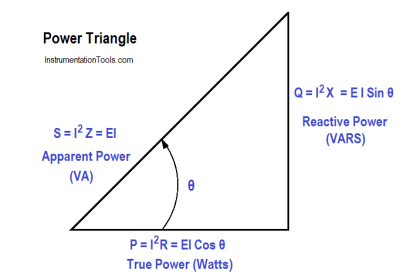
Power factor (pf) is the ratio between true power and apparent power.

True power is the power consumed by an AC circuit, and reactive power is the power that is stored in an AC circuit.

Cosθ is called the power factor (pf) of an AC circuit. It is the ratio of true power to apparent power, where θ is the phase angle between the applied voltage and current sine waves and also between P and S on a power triangle (Figure1).

The below Equation is a mathematical representation of power factor.

Power factor formula

where

cosθ = power factor (pf)
P = true power (watts)
S = apparent power (VA)

Power factor also determines what part of the apparent power is real power. It can vary from 1, when the phase angle is 0°, to 0, when the phase angle is 90°.

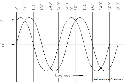
In an inductive circuit, the current lags the voltage and is said to have a lagging power factor, as shown in Figure 2.

Lagging Power Factor

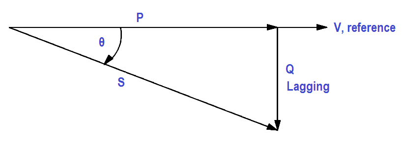
Figure 2 : Lagging Power Factor

In a capacitive circuit, the current leads the voltage and is said to have a leading power factor, as shown in Figure 3.

Leading Power Factor

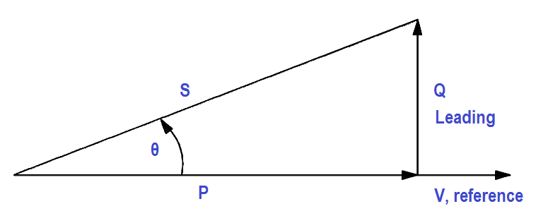
Figure 3 : Leading Power Factor

A mnemonic memory device, “ELI the ICE man,” can be used to remember the voltage/current relationship in AC circuits. ELI refers to an inductive circuit (L) where current (I) lags voltage (E). ICE refers to a capacitive circuit (C) where current (I) leads voltage (E).

Don't Miss Our Updates
Be the first to get exclusive content straight to your email.
We promise not to spam you. You can unsubscribe at any time.
Invalid email address
You've successfully subscribed !

Continue Reading

Simplified Formulas for Parallel Circuit Resistance Calculations
Series and Parallel Inductors
AC Generation Analysis : Effective Values, Phase Angle and Frequency
Shunt-Wound Motor Operation
Y and Delta Resistor Network Calculations
Batteries Theory
Share This Article
Facebook Whatsapp Whatsapp LinkedIn Copy Link
Share
Leave a Comment

Leave a Reply Cancel reply

Your email address will not be published. Required fields are marked *

Stay Connected

128.3kFollowersLike
69.1kFollowersFollow
210kSubscribersSubscribe
38kFollowersFollow

Categories

Explore More

DC Circuit Analysis Node Equations
Parallel Circuit
Series Open Circuit Faults
Shunt-Wound DC Generators
Ammeter
What is a circuit breaker ?
Transformer Current Ratio
4-Wire, Three-Phase Wye Wiring System

Keep Learning

AC Generator Operation

Types of AC Generators

Parallel RLC Circuit

Impedance in RLC Circuits

induction motor torque versus speed

Induction Motor Torque Versus Slip

DC Machine

DC Machines Construction

Using Kirchhoff’s Voltage Law to find Current with one Source

Applying Kirchhoff’s Voltage Law

Generator Action in a Motor

Generator Action in a Motor

Batteries Connected in Parallel

Battery Operation : Series and Parallel

Current in a Capacitor

Capacitance and Capacitive Reactance

Learn More

Electronic Devices & Circuits Objective Questions

Electronic Devices & Circuits Quiz – Set 10

Power Electronics Objective Questions

PWM Inverter Quiz

Hardwired IO and Serial IO - Differences Explained

Hardwired I/O and Serial I/O – Differences Explained

Automatic Transfer Switch

Automatic Transfer Switch (ATS) Using Classic Control Circuit

Electrical & Electronics Measurements Objective Questions

Electrical & Electronics Measurements Objective Questions – Set 3

NDIR GAS ANALYSER WORKING PRINCIPLE ANIMATION

NDIR Gas Analyser Working Principle

Electrical Machines Questions and Answers

Electrical Machines Losses and Efficiency MCQ

Difference Between Emergency STOP and Emergency Power OFF

Difference Between Emergency STOP and Emergency Power OFF

Menu

  • About
  • Privacy Policy
  • Copyright

Quick Links

  • Learn PLC
  • Helping Hand
  • Part Time Job

YouTube Subscribe

Follow US
All rights reserved. Reproduction in whole or in part without written permission is prohibited.
Welcome Back!

Sign in to your account

Username or Email Address
Password

Lost your password?