Inst ToolsInst ToolsInst Tools
  • Courses
  • Automation
    • PLC
    • Control System
    • Safety System
    • Communication
    • Fire & Gas System
  • Instrumentation
    • Design
    • Pressure
    • Temperature
    • Flow
    • Level
    • Vibration
    • Analyzer
    • Control Valve
    • Switch
    • Calibration
    • Erection & Commissioning
  • Interview
    • Instrumentation
    • Electrical
    • Electronics
    • Practical
  • Q&A
    • Instrumentation
    • Control System
    • Electrical
    • Electronics
    • Analog Electronics
    • Digital Electronics
    • Power Electronics
    • Microprocessor
  • Request
Search
  • Books
  • Software
  • Projects
  • Process
  • Tools
  • Basics
  • Formula
  • Power Plant
  • Root Cause Analysis
  • Electrical Basics
  • Animation
  • Standards
  • 4-20 mA Course
  • Siemens PLC Course
Reading: Apparent Power, True Power, Reactive Power & Total Power
Share
Font ResizerAa
Inst ToolsInst Tools
Font ResizerAa
  • Courses
  • Design
  • PLC
  • Interview
  • Control System
Search
  • Courses
  • Automation
    • PLC
    • Control System
    • Safety System
    • Communication
    • Fire & Gas System
  • Instrumentation
    • Design
    • Pressure
    • Temperature
    • Flow
    • Level
    • Vibration
    • Analyzer
    • Control Valve
    • Switch
    • Calibration
    • Erection & Commissioning
  • Interview
    • Instrumentation
    • Electrical
    • Electronics
    • Practical
  • Q&A
    • Instrumentation
    • Control System
    • Electrical
    • Electronics
    • Analog Electronics
    • Digital Electronics
    • Power Electronics
    • Microprocessor
  • Request
Follow US
All rights reserved. Reproduction in whole or in part without written permission is prohibited.
Inst Tools > Blog > Electrical Theory > Apparent Power, True Power, Reactive Power & Total Power

Apparent Power, True Power, Reactive Power & Total Power

Last updated: August 1, 2018 6:52 pm
Editorial Staff
Electrical Theory
No Comments
Share
3 Min Read
SHARE

Apparent Power

Apparent power (S) is the power delivered to an electrical circuit.

The below Equation is a mathematical representation of apparent power.

The measurement of apparent power is in voltamperes (VA).

S=I2Z = IT E

where

S = apparent power (VA)
I = RMS current (A)
E = RMS voltage (V)
Z = impedance (Ω)

True Power

True power (P) is the power consumed by the resistive loads in an electrical circuit.

The below Equation is a mathematical representation of true power.

The measurement of true power is in watts.

P=  I2R = EI cosθ

where

P = true power (watts)
I = RMS current (A) .
E = RMS voltage (V)
R = resistance (Ω)
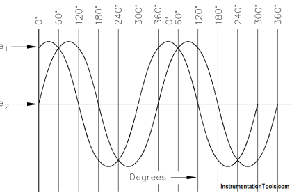
θ = angle between E and I sine waves

Reactive Power

Reactive power (Q) is the power consumed in an AC circuit because of the expansion and collapse of magnetic (inductive) and electrostatic (capacitive) fields.

Reactive power is expressed in volt-amperes-reactive (VAR).

The below Equation is a mathematical representation for reactive power.

Q =  I2X = EI sinθ

where

Q = reactive power (VAR)
I = RMS current (A)
X = net reactance (Ω)
E = RMS voltage (V)
θ = angle between the E and I sine waves

Unlike true power, reactive power is not useful power because it is stored in the circuit itself. This power is stored by inductors, because they expand and collapse their magnetic fields in an attempt to keep current constant, and by capacitors, because they charge and discharge in an attempt to keep voltage constant. Circuit inductance and capacitance consume and give back reactive power.

Reactive power is a function of a system’s amperage. The power delivered to the inductance is stored in the magnetic field when the field is expanding and returned to the source when the field collapses. The power delivered to the capacitance is stored in the electrostatic field when the capacitor is charging and returned to the source when the capacitor discharges.

None of the power delivered to the circuit by the source is consumed. It is all returned to the source. The true power, which is the power consumed, is thus zero. We know that alternating current constantly changes; thus, the cycle of expansion and collapse of the magnetic and electrostatic fields constantly occurs.

Total Power

The total power delivered by the source is the apparent power. Part of this apparent power, called true power, is dissipated by the circuit resistance in the form of heat. The rest of the apparent power is returned to the source by the circuit inductance and capacitance.
Don't Miss Our Updates
Be the first to get exclusive content straight to your email.
We promise not to spam you. You can unsubscribe at any time.
Invalid email address
You've successfully subscribed !

Continue Reading

Transformer Turns Ratio
DC Motor Speed
Three Phase AC Generators
Series Short Circuit Faults
Series and Parallel Inductors
Magnetism
Share This Article
Facebook Whatsapp Whatsapp LinkedIn Copy Link
Share
Leave a Comment

Leave a Reply Cancel reply

Your email address will not be published. Required fields are marked *

Stay Connected

128.3kFollowersLike
69.1kFollowersFollow
210kSubscribersSubscribe
38kFollowersFollow

Categories

Explore More

Reading Electrical Schematics
What is a circuit breaker ?
Motor Controllers
DC Generator Internal Losses
DC Circuit Analysis Node Equations
Power Triangle
Compound Generators
Transformer Operation Under No-Load

Keep Learning

Parallel Circuit Unknown Resistance

Simplified Formulas for Parallel Circuit Resistance Calculations

Phase angle

AC Generation Analysis : Effective Values, Phase Angle and Frequency

Using Kirchhoff’s Voltage Law to find Current with Multiple Battery Sources

Kirchhoff’s Laws

Ohm Meter Circuit

Ohm Meter

3φ AC Power Connections

Three Phase Systems

Three Phase Transformer Connections

Three Phase Transformer Connections

Calculate Power in Series RL Circuit

Calculate Power in Series RL Circuit

Transformer Coil Polarity

Transformer Coil Polarity

Learn More

Power Electronics Objective Questions

Current Source Inverters Objective Questions

phototransistor-circuit

Phototransistor Circuit Example

Process Variable Damping Graph

Process Variable Damping of Transmitter

PLC Program

PLC Program to Heat and Bend Glass Tubes

different flow measurement technologies

Different Flow Measurement Technologies

Orifice Plate Sizing

Orifice Sizing Guidelines and Thumb Rules with Flowchart

Instrumentation Guide

Control and Instrumentation Engineer Study Guide

Cable Float Level Switch Principle

Cable Float Level Switch Working Principle

Menu

  • About
  • Privacy Policy
  • Copyright

Quick Links

  • Learn PLC
  • Helping Hand
  • Part Time Job

YouTube Subscribe

Follow US
All rights reserved. Reproduction in whole or in part without written permission is prohibited.
Welcome Back!

Sign in to your account

Username or Email Address
Password

Lost your password?