Inst ToolsInst ToolsInst Tools
  • Courses
  • Automation
    • PLC
    • Control System
    • Safety System
    • Communication
    • Fire & Gas System
  • Instrumentation
    • Design
    • Pressure
    • Temperature
    • Flow
    • Level
    • Vibration
    • Analyzer
    • Control Valve
    • Switch
    • Calibration
    • Erection & Commissioning
  • Interview
    • Instrumentation
    • Electrical
    • Electronics
    • Practical
  • Q&A
    • Instrumentation
    • Control System
    • Electrical
    • Electronics
    • Analog Electronics
    • Digital Electronics
    • Power Electronics
    • Microprocessor
Search
  • Books
  • Software
  • Projects
  • Process
  • Tools
  • Basics
  • Formula
  • Power Plant
  • Root Cause Analysis
  • Electrical Basics
  • Animation
  • Standards
  • 4-20 mA Course
  • Siemens PLC Course
Reading: Portable Gas Detectors Calibration Procedure
Share
Notification Show More
Font ResizerAa
Inst ToolsInst Tools
Font ResizerAa
  • Courses
  • Design
  • PLC
  • Interview
  • Control System
Search
  • Courses
  • Automation
    • PLC
    • Control System
    • Safety System
    • Communication
    • Fire & Gas System
  • Instrumentation
    • Design
    • Pressure
    • Temperature
    • Flow
    • Level
    • Vibration
    • Analyzer
    • Control Valve
    • Switch
    • Calibration
    • Erection & Commissioning
  • Interview
    • Instrumentation
    • Electrical
    • Electronics
    • Practical
  • Q&A
    • Instrumentation
    • Control System
    • Electrical
    • Electronics
    • Analog Electronics
    • Digital Electronics
    • Power Electronics
    • Microprocessor
Follow US
All rights reserved. Reproduction in whole or in part without written permission is prohibited.
Inst Tools > Blog > Calibration > Portable Gas Detectors Calibration Procedure

Portable Gas Detectors Calibration Procedure

Last updated: September 20, 2018 9:41 am
Editorial Staff
Calibration Fire & Gas System
1 Comment
Share
5 Min Read
SHARE

Portable Gas Detectors Calibration Procedure :

According to AS/NZS 60079.29.2:2008 (Gas Detectors – Selection, installation, use and maintenance of detectors for flammable gases and oxygen) a portable gas monitor should be regularly calibrated by a competent person according to the manufacturer’s instructions.

A gas monitor/detector looses sensitivity over time due to aging, exposure to high concentrations of gases, sensor poisoning etc and so the accuracy of the gas monitor must be verified on a regular basis. This can be done by performing a calibration that will ensure the gas monitor is operating correctly

Calibration Frequency :

The frequency of span calibration is best determined by local standards, company policies and industry best practices.

The calibration frequency should be determined by the level of risk. A high risk situation will require a higher frequency of calibration in comparison to a low risk situation. Best practice is to test the gas monitor with a known concentration of gas before each use (bump test/challenge test).

Another way to determine the calibration frequency is to check the response of the gas monitor daily in the intended atmosphere for a pre-determined time (example being 10 days). If there is nothing in the atmosphere that is causing a loss of sensitivity to the installed sensors then these tests indicate that there is no need to make any adjustments and the time between checks can be lengthened.

Portable Gas Detectors Calibration Procedure

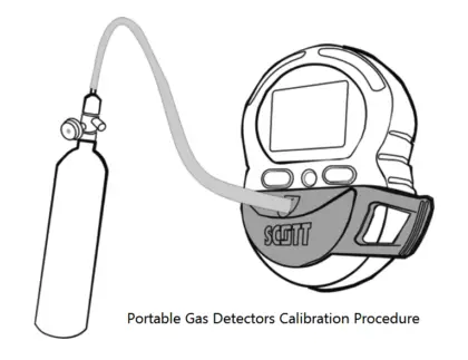
Image Credits : scottsafety

Calibration Procedure :

The calibration procedure includes both a zero calibration (fresh air calibration) and sensor calibration with known concentrations of gas (span calibration).

  • Zero calibration is performed to establish baseline readings of atmospheres that are known to be free of toxic and combustible gases.
  • Baseline readings are zero for carbon monoxide, hydrogen sulphide, combustibles and 20.9% for oxygen.
  • Span calibration is the adjustment of the gas monitors response to match that of a known concentration of gas. Sensors can lose sensitivity through normal degradation, exposure to high gas concentrations or sensor poisoning.
  • The Span calibration is performed to ensure the gas monitor detects the target gases within specific operating parameters.

Equipment required to perform a manual span calibration:

  • Calibration gas with the following concentrations (concentrations may vary depends on make/model)
    • 50 ppm CO
    • 25 ppm H2S
    • 1.62 Vol% CH4 (32% LEL)
    • 19 Vol% O2
  • Tygon tubing
  • Gas flow regulator able to provide 0.5 LPM
  • Calibration adapter

ZERO calibration procedure (also known as fresh air calibration)

  • Verify the ambient air is free of toxic or combustible gases. If air is not free or cannot be verified free, obtain Zero Air gas cylinder.
  • Power on the device
  • Press and hold the Right Operating Button until PLEASE WAIT displays.
  • The zero calibration is now in progress
  • If display indicates “IS AIR CLEAR” verify the atmosphere is clean and press the Right Operating Button to start the Zero Calibration.
  • Wait for device to complete Zero Calibration.

If passed, the LCD displays APPLY GAS to being the SPAN calibration

SPAN calibration procedure

Before beginning the calibration process it is important to check that the calibration gas concentrations set on the Protégé device match the actual gas concentration on the gas cylinder.

When APPLY GAS is displayed :

  • Attach the flow regulator to the gas cylinder and verify cylinder pressure
  • Connect the tygon tubing to both the regulator and calibration adapter
  • If the password screen appears enter the 4-digit password using the left operation button to scroll through the numeric characters and the right operation button to accept the entry.
  • Attach the calibration adaptor to the gas monitor and apply the gas from the regulator.
  • Once each sensor is calibrated, the device displays CAL PASSED then REMOVE GAS.
  • Remove Calibration Adapter and wait for the device’s main display to return before turning off the device.

Note : Calibration principle almost same for any make/model, depends on gas detectors model the buttons/display texts will vary.

Source : scottsafety

Don't Miss Our Updates
Be the first to get exclusive content straight to your email.
We promise not to spam you. You can unsubscribe at any time.
Invalid email address
You've successfully subscribed !

Continue Reading

Load Cell Healthiness Checks
Open Tank DP Level Transmitter Calibration
How to do calibration checks of vibration Probe, extension cable and vibration monitor
Impulse Line Pressure Testing Procedure
Standard Gas Detection Definitions
Hybrid Level Measurement Principle, Selection, Installation, Limitations and Calibration
Share This Article
Facebook Whatsapp Whatsapp LinkedIn Copy Link
Share
1 Comment
  • Amin Rushi says:
    July 11, 2017 at 7:02 am

    Very useful for Analyzer syatem understanding.

    Reply

Leave a Reply Cancel reply

Your email address will not be published. Required fields are marked *

Stay Connected

128.3kFollowersLike
69.1kFollowersFollow
208kSubscribersSubscribe
38kFollowersFollow

Categories

Explore More

Overview of Fire/Smoke/Flame/Heat/Gas Detectors
Step by Step Guide for Gas Flow Meter Calibration
Difference between Accuracy, Tolerance, Uncertainty, and Error
How to Calibrate Temperature Switch? – Instrument Basics
Single Position Calibration of Temperature Bath
Pressure Gauge Calibration Procedure
What is a Fire Pump? – Definition, Principle, Types, Comparison
What is Bump Testing ?

Keep Learning

level-transmitter-calibration-procedure

Level Transmitter Calibration Procedure

Difference between Calibration and Ranging

Difference between Calibration and Ranging

Differential Pressure Sensor Calibration

Differential Pressure Sensors Calibration Procedure

Gases LEL and UEL

What is Lower Explosive Limit & Upper Explosive Limit ?

History of Measurement

History of Measurement

Calibration of Pyrometers using Black Body

Calibration of Pyrometers using Black Body

Carbon Monoxide Gas Hazards

Carbon Monoxide Gas Hazards

Magnehelic Gauge Calibration

Magnehelic Gauge Calibration

Learn More

Configure Analog Inputs and Outputs in Delta PLC

How to Configure Analog Inputs and Outputs in Delta PLC?

Pressure Transmitter Basics

Pressure Transmitter Applications

Electromagnetic Fields Objective Questions

Electromagnetic Field Test Questions

PLC Emergency Stop Example Program

PLC Emergency Stop Example Program

Twisted Pair Cable Noise Supression

Why We use Shielded Cable and Twisted Pair Cables ?

PLC Stop - Start Circuit

Introduction to PLC Ladder Diagrams

ungrounded-or-isolated-neutral-system-disadvantages

Ungrounded or Isolated Neutral System Disadvantages

Types of PLC

Types of PLC

Follow US
All rights reserved. Reproduction in whole or in part without written permission is prohibited.
Welcome Back!

Sign in to your account

Username or Email Address
Password

Lost your password?