Inst ToolsInst ToolsInst Tools
  • Courses
  • Automation
    • PLC
    • Control System
    • Safety System
    • Communication
    • Fire & Gas System
  • Instrumentation
    • Design
    • Pressure
    • Temperature
    • Flow
    • Level
    • Vibration
    • Analyzer
    • Control Valve
    • Switch
    • Calibration
    • Erection & Commissioning
  • Interview
    • Instrumentation
    • Electrical
    • Electronics
    • Practical
  • Q&A
    • Instrumentation
    • Control System
    • Electrical
    • Electronics
    • Analog Electronics
    • Digital Electronics
    • Power Electronics
    • Microprocessor
  • Request
Search
  • Books
  • Software
  • Projects
  • Process
  • Tools
  • Basics
  • Formula
  • Power Plant
  • Root Cause Analysis
  • Electrical Basics
  • Animation
  • Standards
  • 4-20 mA Course
  • Siemens PLC Course
Reading: PLC Scan Time
Share
Notification Show More
Font ResizerAa
Inst ToolsInst Tools
Font ResizerAa
  • Courses
  • Design
  • PLC
  • Interview
  • Control System
Search
  • Courses
  • Automation
    • PLC
    • Control System
    • Safety System
    • Communication
    • Fire & Gas System
  • Instrumentation
    • Design
    • Pressure
    • Temperature
    • Flow
    • Level
    • Vibration
    • Analyzer
    • Control Valve
    • Switch
    • Calibration
    • Erection & Commissioning
  • Interview
    • Instrumentation
    • Electrical
    • Electronics
    • Practical
  • Q&A
    • Instrumentation
    • Control System
    • Electrical
    • Electronics
    • Analog Electronics
    • Digital Electronics
    • Power Electronics
    • Microprocessor
  • Request
Follow US
All rights reserved. Reproduction in whole or in part without written permission is prohibited.
Inst Tools > Blog > PLC Tutorials > PLC Scan Time

PLC Scan Time

Last updated: March 4, 2021 12:07 pm
Editorial Staff
PLC Tutorials
4 Comments
Share
5 Min Read
SHARE

What is Scan Time?

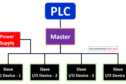
Every control system will take some time to execute its operation. Likewise, PLCs also takes time to perform a task. In simple terms, PLCs mainly has 3 parts which are input modules, output modules, and processor (CPU).

Contents
What is Scan Time?Definition of PLC Scan TimeWhy the Scan time Important?

The input modules will read the status of switches, transmitters, and gives the data to the processor. The processor will execute the logic as per the user program. The processor will give the command to the output modules. The output modules are connected with final control elements like control valves, motor control feeders, etc.

The inputs and outputs may be in the form of NO, NC, 4-20mA, or a Bit/Pulse. So, the above all mentioned steps require some time in PLC which means for reading inputs, solve the logic, and write output, each step required some time which is nothing but the PLC scan time.

Definition of PLC Scan Time

Time taken by the PLC to read the inputs, solve the Logic, and to write the output is called a PLC Scan Time.

These functions work in the loop it may vary its time taken for execution from 0ms to 150ms to a large till 1000ms.

The variation in scan time depends on the following factors:

  • Number of inputs
  • Length of logic/Loops in program
  • Number of Outputs

Let’s get clear the concept by the following example;

In PLC, we have an analog input card, these analog signals need to be converted in digital format so that the processor can read it and perform an action.

Say If 1 channel generally needs a 3ms time so, if we used a 4 channel to PLC then the scan time will be 4 X 3=12ms.

Why the Scan time Important?

Suppose we have a PLC whose scan time is 5ms, and we need to assign an input for an encoder which generates a pulse every 1ms time. Refer below figure (a).
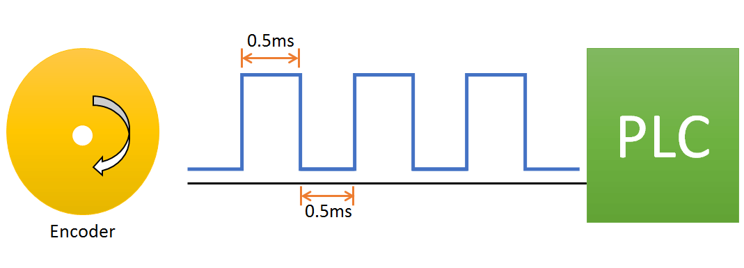
Why the PLC Scan time is Important

Figure: a

In the graph below, as you can see the PLC takes a 0.3ms time to read input, 0.3ms time to write output, and 4.4ms time to executive logic. I.e. total 5ms scan time is required by PLC.
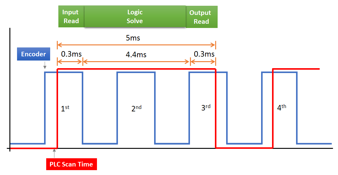
PLC Scan Time

Figure: b

As we can see the encoder pulse start after 0.5ms and PLC scan time starts with 0ms. The PLC will read the first pulse of the encoder which is at 0.5ms but after the first pulse as soon as the second pulse which will be at 1ms, the PLC will not be able to read this input because the PLC input read scan time is 0.3ms only.

So at each new scan time, the PLC will read only the first pulse of the encoder and other pulses will be neglected by PLC because PLC scan time is Greater than Encoder time. These are a serious issue for the process.

What if I have already a PLC whose scan time is greater than an encoder?

In the PLC software there is Instruction, by which you can avoid the above problem they are as followed;

  • Immediate Instruction – Input Immediate, Output Immediate
  • Interrupts instruction.

These instructions are mainly seen in Siemens Old PLC’s.

The Instruction works such that the input immediate will pause the logic execution step and read the Inputs again and again and then continue the logic step, same the other Instruction also works respectively.

Author: Jadhav Amit R

If you liked this article, then please subscribe to our YouTube Channel for PLC and SCADA video tutorials.

You can also follow us on Facebook and Twitter to receive daily updates.

Read Next:

  • FB Block in Siemens PLC
  • PLC Input Output Modules
  • One-Shot Rising PLC Program
  • Midline Instruction in Siemens
  • Choose Right Fuse for a Panel
Don't Miss Our Updates
Be the first to get exclusive content straight to your email.
We promise not to spam you. You can unsubscribe at any time.
Invalid email address
You've successfully subscribed !

Continue Reading

Create PLC Program based on Logic Circuit
Download a Ladder logic program to GE PLC
Siemens PLC Organization Blocks (OB)
Redundant Automation Systems – Need and Advantages
FB Block in Siemens PLC Programming
What is a Tower Lamp? – Light Tower in Industrial Automation
Share This Article
Facebook Whatsapp Whatsapp LinkedIn Copy Link
Share
4 Comments
  • Pradeep says:
    June 8, 2020 at 2:13 pm

    Good example. Whether there are such logics in a DCS ?

    Reply
  • Amit jadhav says:
    July 22, 2020 at 4:27 pm

    Yes, usually the design of DCS scan time starts from 0.5ms to greater upto 500ms these are adjustable according to process.

    Reply
  • Sunny Madas says:
    July 22, 2020 at 4:35 pm

    Verry important information necessary for Instrumentation and plc selection

    Reply
  • Cláudio Timóteo de Souza says:
    April 6, 2021 at 1:41 pm

    Is scanning time a clock?
    Isn’t it symmetrical? duty cycle greater than 50%?
    During level 0 it do nothing?
    The scan time is generally synchronous?
    If I use a bit memory contact NC on series with a coil, I get de scan time?

    Thanks!

    Reply

Leave a Reply Cancel reply

Your email address will not be published. Required fields are marked *

Stay Connected

128.3kFollowersLike
69.1kFollowersFollow
210kSubscribersSubscribe
38kFollowersFollow

Categories

Explore More

How to Use Symbol Factory Software for Graphic Design in HMI or SCADA?
Types of Industrial Control Systems
#14 PLC Best Practices – Restrict Third-party Data Interfaces
How to Take Program Backup from Physical PLC? – Siemens PLC
PLC FBD Program for Bottle’s Capping with Rotating Mechanism
How to Select a SCADA for New PLC Project?
Compare Modbus, Fieldbus, and Profibus
PLC Program for Counting Moving Objects on Conveyor

Keep Learning

Namur Digital Input Card

What is Namur Digital Input Card?

SFC Language in PLC Programming

SFC Language in PLC Programming

Analog Measurement using Ladder Logic

Analog Measurement using Ladder Logic

PLC Examples for calling functions in SCL

How to Insert Block Calls in SCL Language?

PLC Programming in Bottle Filling Process

Applications of PLC Programming in Bottle Filling Process

PLC analog output card

PLC Analog I/O and Network I/O

PLC Automation Memory

What is NOR Flash Memory in PLC?

Augmented Reality and Virtual Reality in Industrial Automation

Augmented Reality and Virtual Reality in Industrial Automation

Learn More

Rectifiers & Converters MCQ

Rectifiers & Converters MCQ – Multiple Choice Questions

Flow Meters Troubleshooting

Turbine Flow Meters Troubleshooting

Where should we terminate the shield and why

Where should we Terminate the Cable Shields ?

Single-Acting Air Compressor Cylinder

Reciprocating Compressors

Two-Conveyor PLC Control System

Basic Conveyor System for Product Handling in Omron PLC

DC Circuit

Main differences between Sinking and Sourcing Circuits

Butterfly Valve Failure caused Fire

Butterfly Valve Failure Caused Serious vicinity Heavy Fire

How to identify location of Fire Detectors

How to identify location of Fire Detectors

Menu

  • About
  • Privacy Policy
  • Copyright

Quick Links

  • Learn PLC
  • Helping Hand
  • Part Time Job

YouTube Subscribe

Follow US
All rights reserved. Reproduction in whole or in part without written permission is prohibited.
Welcome Back!

Sign in to your account

Username or Email Address
Password

Lost your password?