List of questions in the industrial automation, PLC programming, and SCADA.
PLC Question Bank
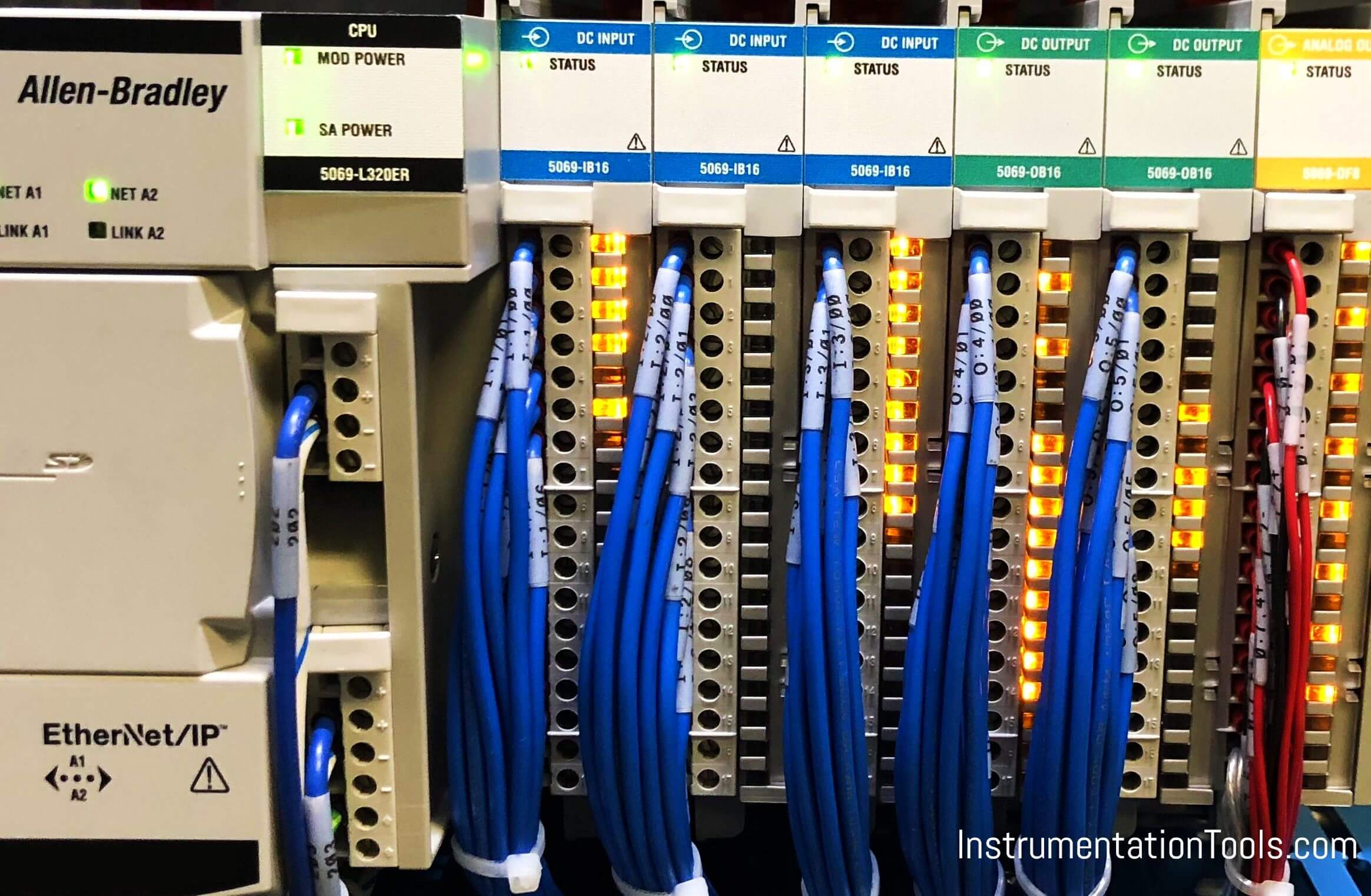
Automation
1) State the need of automation
2) State the requirements of Automation.
3) State the advantages and disadvantages of Automation
PLC
1) List any six brands of PLCs available in the market.
2) Explain the function of ADC and DAC in PLC.
3) Explain the types of PLCs
4) Explain the standard specifications of PLC.
5) Explain the function of the Power supply module inside compact PLC.
6) Explain the function of Bus system in PLC.
7) State advantages and disadvantages of PLC.
8) Compare PC and PLC.
9) Draw a block diagram of PLC and explain in brief.
10) State the components of CPU and their functions in PLC.
11) Explain Input module and output module in PLC.
12) Comparison between Relay based and PLC based control systems
13) Explain SCAN cycle of PLC
Programming PLC
1) What do you mean by Rung in PLC?
2) State the various PLC programming languages.
3) Explain the Anatomy of a Ladder Program.
4) Draw a ladder program of starting of Induction Motor.
5) Draw a ladder program of a stepper motor.
6) Explain the series-parallel execution of Rung in the ladder diagram.
7) Explain how ladder logic is executed with the help of an example.
8) Explain Bit type instructions- XIC, XIO, OTE, OTL, OUT, OSR.
9) Explain Logical instructions- OR, AND, NOT, XOR.
10) Explain Comparison instructions- EQU, NEQ, LES, LEQ, GRT, GERQ, LIM.
11) Explain Timer instructions- TON, TOFF, RTO.
12) Explain Counter instructions- CTU, CTD.
13) Explain Scaling instructions- SCP.
14) Write a PLC program to control traffic lights.
15) Write a PLC program for the bottle filling plant.
16) Write a PLC program for diesel generator set control
17) Write a PLC program to control a motor.
SCADA
1) What is HMI?
2) Define SCADA.
3) List the SCADA software used in the industry.
4) Compare SCADA and PLC.
5) Compare SCADA and HMI.
6) Explain SCADA Network.
More Questions
1) Explain the following terms in the context of PLC. a. Execution time b. Isolation c. Processing time d. Dry contacts e. Master Reset
2) Explain ladder logic programming Technique with symbols of PLC.
3) Explain in detail Analogue and Digital I/O module.
4) Why different types of I/O modules are required to be interfaced with PLC? Explain functioning of PLC input and output module with neat diagram.
5) Explain following PLC function with suitable example. a. Less than COMPARE function b. Jump to Subroutine function.
6) List and explain various data move functions available in PLC.
7) Discuss the difference in operation between following instructions a. MCR b. Timer – Retentive Timer
8) Explain the function of UP-DOWN counter with the help of timing diagram.
9) Draw the ladder diagram using the timing block to turn on the motor after the delay of 5 seconds after pressing the start switch. And turn on the lamp after the delay of 5 seconds when the motor is off. Motor should be off after delay of 3 seconds when stop switch is turned on.
10) Develop the Ladder Logic Diagram for a motor with following: NO start button, NC stop button Thermal overload switch opens on high temperature, green light when running, and red light for thermal overload.
11) Develop a Ladder Logic Diagram to ON & OFF a motor with single button; ON at first press and OFF at second press.
12) When a start button is depressed, M goes on. Five seconds later N goes on. When stop is pushed, both M and N goes off. In addition 6 seconds after M and N goes off, fan F, which had previously been off, goes on. F remains on until the start button is again depressed, at which time it goes off.
13) An automatic car parking system, when the parking area is full with 10 cars the red bulb at entry should ON to indicate it is full. If the number of car within the parking area is less than 10 the green bulb should ON to indicate that the space of parking is available.
14) A timer is to turn on a fan switch 8.6 sec after a wall switch is turned ON. If the wall switch is turned OFF during the 8.6 sec. time interval, the timer is to reset to zero seconds, so that when the wall switch is again turned ON, the delay is the full 8.6 sec. Prepare Ladder Logic Diagram.
Author: Dr.Mahesh S.Narkhede
Share your answers with us through the below comments section.
If you liked this article, then please subscribe to our YouTube Channel for PLC and SCADA video tutorials.
You can also follow us on Facebook and Twitter to receive daily updates.
Read Next:






stay out of my territory