Inst ToolsInst ToolsInst Tools
  • Courses
  • Automation
    • PLC
    • Control System
    • Safety System
    • Communication
    • Fire & Gas System
  • Instrumentation
    • Design
    • Pressure
    • Temperature
    • Flow
    • Level
    • Vibration
    • Analyzer
    • Control Valve
    • Switch
    • Calibration
    • Erection & Commissioning
  • Interview
    • Instrumentation
    • Electrical
    • Electronics
    • Practical
  • Q&A
    • Instrumentation
    • Control System
    • Electrical
    • Electronics
    • Analog Electronics
    • Digital Electronics
    • Power Electronics
    • Microprocessor
  • Request
Search
  • Books
  • Software
  • Projects
  • Process
  • Tools
  • Basics
  • Formula
  • Power Plant
  • Root Cause Analysis
  • Electrical Basics
  • Animation
  • Standards
  • 4-20 mA Course
  • Siemens PLC Course
Reading: PLC Pump Control: 10 seconds ON & 20 seconds OFF
Share
Font ResizerAa
Inst ToolsInst Tools
Font ResizerAa
  • Courses
  • Design
  • PLC
  • Interview
  • Control System
Search
  • Courses
  • Automation
    • PLC
    • Control System
    • Safety System
    • Communication
    • Fire & Gas System
  • Instrumentation
    • Design
    • Pressure
    • Temperature
    • Flow
    • Level
    • Vibration
    • Analyzer
    • Control Valve
    • Switch
    • Calibration
    • Erection & Commissioning
  • Interview
    • Instrumentation
    • Electrical
    • Electronics
    • Practical
  • Q&A
    • Instrumentation
    • Control System
    • Electrical
    • Electronics
    • Analog Electronics
    • Digital Electronics
    • Power Electronics
    • Microprocessor
  • Request
Follow US
All rights reserved. Reproduction in whole or in part without written permission is prohibited.
Inst Tools > Blog > PLC Tutorials > PLC Pump Control: 10 seconds ON & 20 seconds OFF

PLC Pump Control: 10 seconds ON & 20 seconds OFF

Design a program for PLC pump control such that the pump must be turned ON for 10 seconds and turned OFF for 20 seconds.

Last updated: April 8, 2024 3:38 pm
Editorial Staff
PLC Tutorials
No Comments
Share
4 Min Read
SHARE

Design a program for PLC pump control such that the pump must be turned ON for 10 seconds and turned OFF for 20 seconds.

Contents
PLC Pump ControlExpert PLC TrainingInputsOutputsPump Run for 10 seconds & OFF for 20 seconds LogicProgram DescriptionPLC Program Result

Note: The plc programming example is prepared for the engineers who are interested in learning the ladder logic with basics.

PLC Pump Control

Problem Statement:

Design a PLC ladder logic for the following application.

We are using one toggle switch to control the pump.

Turn ON the pump for 10 seconds and then turn OFF the pump for 20 seconds and repeat this cycle.

Expert PLC Training

Our PLC training videos explain the basic concepts and PLC programming for beginners with detailed explanations.

PLC Programming for Pump Running Cycle with Time Delay

Inputs

The required input is listed below.

Start button: I0.0

Outputs

The required output is listed below.

Pump: Q0.0

Pump Run for 10 seconds & OFF for 20 seconds Logic
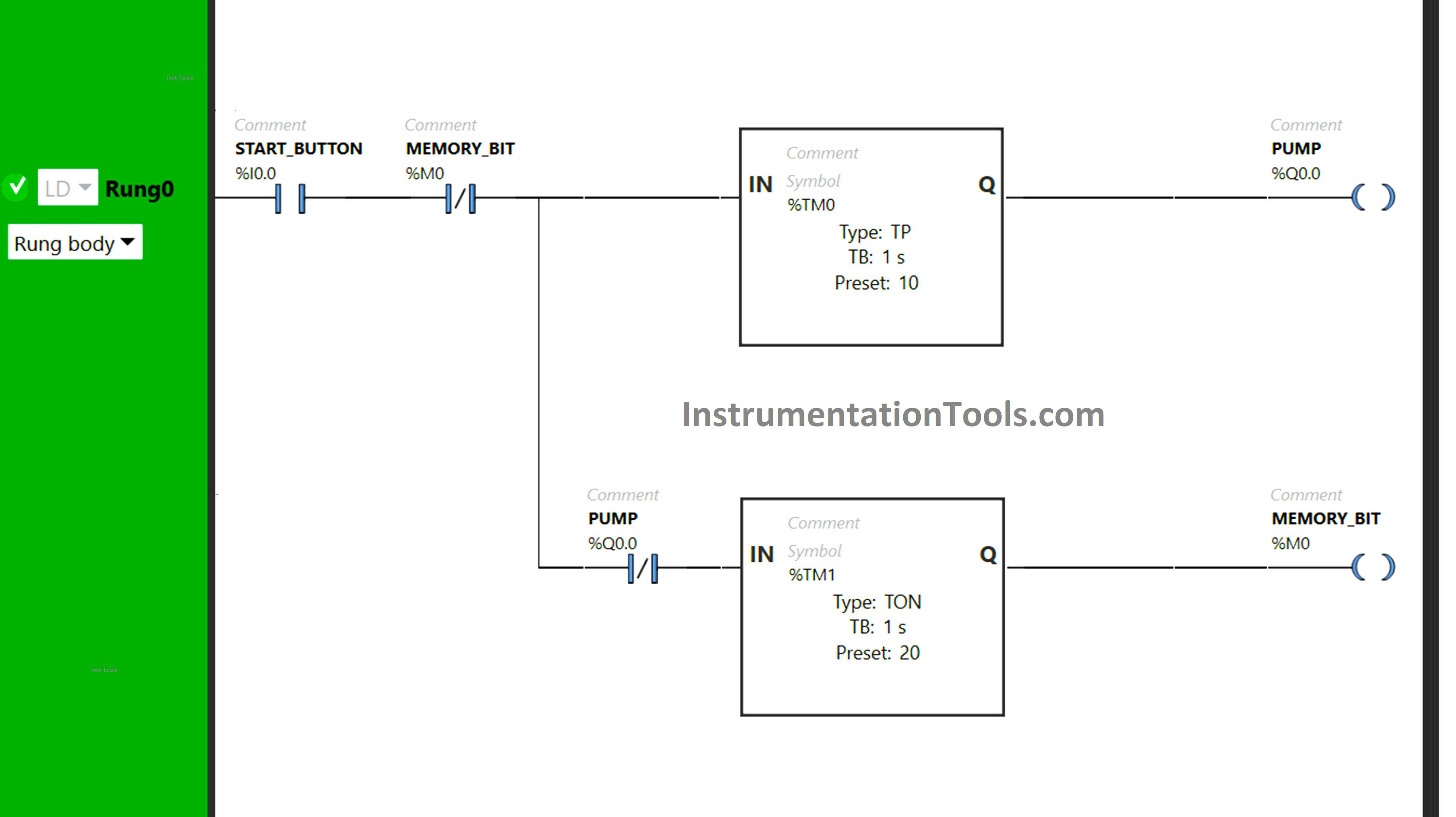
PLC Pump Control

Program Description

We used Normally Open Contact for the Start button.

Two Timer Function Blocks Type TON and TP are used for the Pump and memory bit.

Timer Function Block type TP is used to keep the Pump ON for 10 seconds.

Timer Function Block type TON is used for the Memory bit to turn it ON after a delay of 20 seconds.

PLC Program Result

When the Start button is turned ON, the signal will flow also through the Normally Closed Contact that is used for memory bit as it is false state. Timer functional block type TP (TM0) will allow the signal to flow for a period of 10 seconds only.
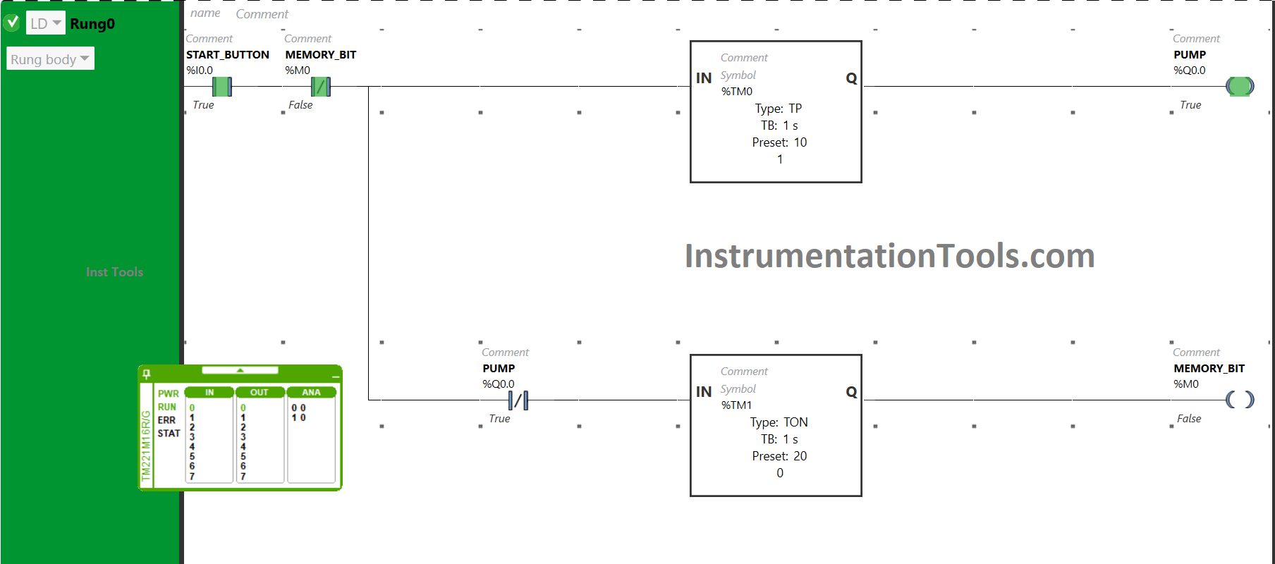
PLC Programming Example on Pump Cycling

As a result, the pump will be turned ON. After 10 seconds, the signal will not flow because of the Timer functional block type TP (TM0). And pump will turn OFF after being ON for 10 seconds.
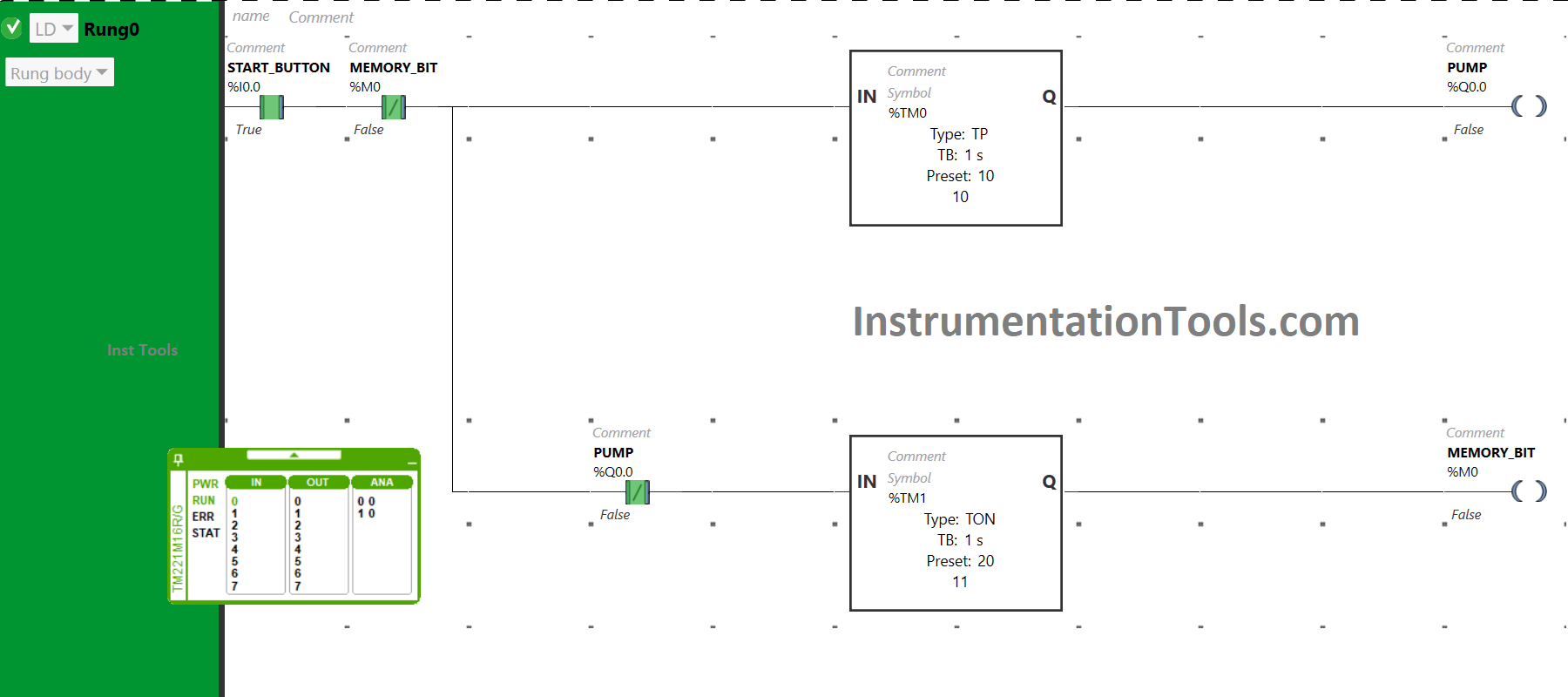
PLC Programming for Pump Running Cycle with Time Delay

When the Start button is turned ON and when the pump gets turned OFF after being ON for 10 seconds, the signal will flow through the Normally Closed contact used for PUMP. There will be a delay of 20 seconds and after that memory bit gets true. In those 20 seconds, the motor will remain OFF.

After a delay of 20 seconds, the coil used for the memory bit becomes true, and the Normally Closed Contact used for the Memory Bit will also become true. The Normally Closed Contact in its true state will break the circuit.

As a result, the coil used for the coil memory bit becomes false which in turn makes the Normally Closed Contact used for the memory bit false. And the signal will again pass to the pump and it will be turned ON for 10 seconds. After that, it will remain OFF for 20 seconds and then it will repeat the process again and again.
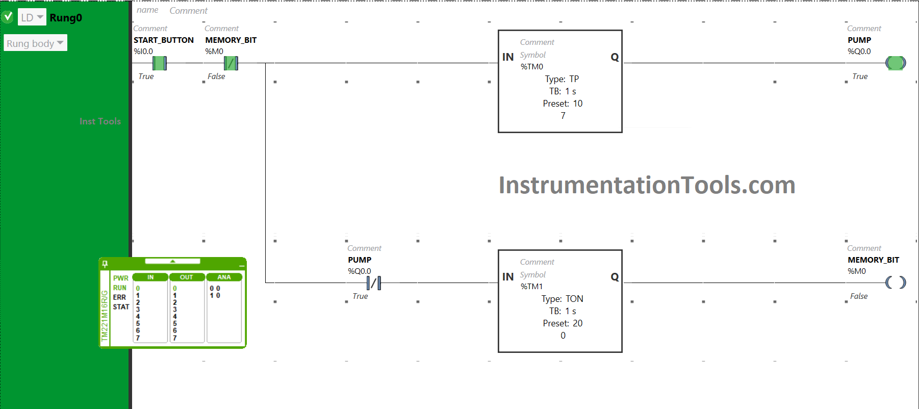
How PLC is used for timed switch operations

If you liked this article, please subscribe to our YouTube Channel for PLC and SCADA video tutorials.

You can also follow us on Facebook and Twitter to receive daily updates.

Read Next:

  • PLC Programming Example with Motor
  • PLC Push Button to Turn ON or OFF Output
  • PLC Code to Start & Stop Motor and Pump
  • Electrical Ladder Diagram Control with Timers
  • Controlling the PLC Output using Push Buttons
Don't Miss Our Updates
Be the first to get exclusive content straight to your email.
We promise not to spam you. You can unsubscribe at any time.
Invalid email address
You've successfully subscribed !

Continue Reading

Advanced PLC Conveyor Control: Forward and Reverse Rotation
PLC Program Examples
Difference Between Static and Temp Memory in Siemens PLC TIA Portal
Schneider PLC Example: Control Lamps Sequences
Testing and Validation in PLC Development
Basic PLC Ladder Programming Example
Share This Article
Facebook Whatsapp Whatsapp LinkedIn Copy Link
Share
Leave a Comment

Leave a Reply Cancel reply

Your email address will not be published. Required fields are marked *

Stay Connected

128.3kFollowersLike
69.1kFollowersFollow
210kSubscribersSubscribe
38kFollowersFollow

Categories

Explore More

Door Locking System – PLC Applications Examples
PLC Multiple Outputs Configuration
PLC Program for Control Valve Scaling
Types of SCADA System Architecture
Interposing Relay Panel (IRP) – Wiring and Testing Requirements
Down Counter PLC Program
PLC Program for Ceramic Burning Oven Conveyor System
PLC Techniques for I/O Mapping

Keep Learning

V1000 Family Programming Simulator Tool

VFD Simulator Download – Free Yaskawa V1000 Software

Redundant system communication cable

What is Interface Module in Siemens PLC?

Automatic Box Filling System using PLC Programming

Automatic Box Filling System using PLC Programming

Types of Cables used in Industrial Automation

Types of Cables used in Industrial Automation

FIFO and LIFO Sequences in PLC

What are FIFO and LIFO Sequences in PLC?

Create Ladder Diagram from Boolean Logic

Create Ladder Diagram from Boolean Logic

Preventa XPS MC, XPS MP - Safety controllers

High-end Programmable Logic Controller – Schneider PLC

Communicate between the PLC program and HMI program

Design a Program Using Studio 5000 and FactoryTalk View Studio

Learn More

Different Control Modes of Air Handling Unit (AHU)

Control Modes of Air Handling Unit (AHU) – HVAC Basics

Installation and Maintenance of Control Valves

Installation and Maintenance of Control Valves

User Defined Data Types - UDT

User Defined Data Types (UDT) – Purpose, Need, Tutorial

What is a Rotary Actuator

Difference Between Linear Actuator and Rotary Actuator

Understanding RS-485 Communication

Understanding RS-485 Communication

Power Triangle

Apparent Power, True Power, Reactive Power & Total Power

How to Update the Firmware Version of your PLC

How to Update the Firmware Version of your PLC? – TIA Portal

Why is IGBT used in VFD

Why is IGBT used in VFD?

Menu

  • About
  • Privacy Policy
  • Copyright

Quick Links

  • Learn PLC
  • Helping Hand
  • Part Time Job

YouTube Subscribe

Follow US
All rights reserved. Reproduction in whole or in part without written permission is prohibited.
Welcome Back!

Sign in to your account

Username or Email Address
Password

Lost your password?