Inst ToolsInst ToolsInst Tools
  • Courses
  • Automation
    • PLC
    • Control System
    • Safety System
    • Communication
    • Fire & Gas System
  • Instrumentation
    • Design
    • Pressure
    • Temperature
    • Flow
    • Level
    • Vibration
    • Analyzer
    • Control Valve
    • Switch
    • Calibration
    • Erection & Commissioning
  • Interview
    • Instrumentation
    • Electrical
    • Electronics
    • Practical
  • Q&A
    • Instrumentation
    • Control System
    • Electrical
    • Electronics
    • Analog Electronics
    • Digital Electronics
    • Power Electronics
    • Microprocessor
  • Request
Search
  • Books
  • Software
  • Projects
  • Process
  • Tools
  • Basics
  • Formula
  • Power Plant
  • Root Cause Analysis
  • Electrical Basics
  • Animation
  • Standards
  • 4-20 mA Course
  • Siemens PLC Course
Reading: PLC Program for Water Level Control Logic
Share
Font ResizerAa
Inst ToolsInst Tools
Font ResizerAa
  • Courses
  • Design
  • PLC
  • Interview
  • Control System
Search
  • Courses
  • Automation
    • PLC
    • Control System
    • Safety System
    • Communication
    • Fire & Gas System
  • Instrumentation
    • Design
    • Pressure
    • Temperature
    • Flow
    • Level
    • Vibration
    • Analyzer
    • Control Valve
    • Switch
    • Calibration
    • Erection & Commissioning
  • Interview
    • Instrumentation
    • Electrical
    • Electronics
    • Practical
  • Q&A
    • Instrumentation
    • Control System
    • Electrical
    • Electronics
    • Analog Electronics
    • Digital Electronics
    • Power Electronics
    • Microprocessor
  • Request
Follow US
All rights reserved. Reproduction in whole or in part without written permission is prohibited.
Inst Tools > Blog > PLC Tutorials > PLC Program for Water Level Control Logic

PLC Program for Water Level Control Logic

Design a PLC program for water level control of a storage tank by turning a discharge pump ON and OFF based on Level Switch status.

Last updated: November 2, 2023 4:46 pm
Editorial Staff
PLC Tutorials
4 Comments
Share
2 Min Read
SHARE

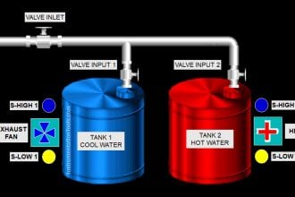
Design a PLC program to control the level of a water storage tank by turning a discharge pump ON and OFF based on Low and High levels.

Contents
PLC Program for Water Level ControlLogic DescriptionPLC Ladder LogicManual Mode Selected, OFF Position and Water at Low LevelManual Mode Selected & Water between Low & High LevelsAuto Mode Selected & High-Level Switch Activated

PLC Program for Water Level Control

Ladder Logic for Water Level Control

Logic Description

  • Auto : if Auto Mode selected in Local Control Panel, then pump will be logically controlled based on Low Level Switch and High Level Switch
  • Manual : if Manual Mode Selected in Local Control Panel, then irrespective of Low Level Switch & High Level Switch Status, Pump will be controlled manually using ON/OFF button in Local Control Panel.
  • When the water level reaches low level then pump will be stopped.
  • if the level of the water reaches high point, the pump will started so that the water can be drained and thus lowering the level.
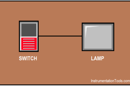
  • Indication Panel : This panel contains LED’s to show the status of the water level control. It has Pump Running, Low Level & High Level Signals
  • If pump is running then the Pump Running status lamp will be ON.
  • then, if Low Level Switch activated then Low Level Status lamp will be ON.
  • if High Level Switch activated then High Level Status lamp will be ON.
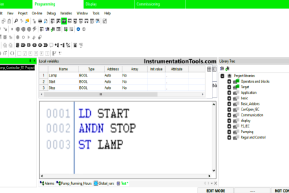
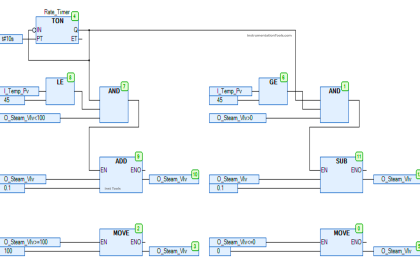
PLC Ladder Logic

Manual Mode Selected, OFF Position and Water at Low Level

PLC Water Level Logic

Manual Mode Selected & Water between Low & High Levels

Water Level Control using PLC

Auto Mode Selected & High-Level Switch Activated

Level Control PLC Logic

If you liked this article, then please subscribe to our YouTube Channel for PLC and SCADA video tutorials.

You can also follow us on Facebook and Twitter to receive daily updates.

Read Next:

  • Process Control Fundamentals
  • Mixing Tank PLC Ladder Logic
  • Automation Engineers Questions
  • Fan Control Unit System using PLC
  • PLC Electric Motor Interlocks
Don't Miss Our Updates
Be the first to get exclusive content straight to your email.
We promise not to spam you. You can unsubscribe at any time.
Invalid email address
You've successfully subscribed !

Continue Reading

Instrumentation and Control Project Packages – Detail Engineering
Electrical and Instrumentation – Automation Pre-engineering Documents
Single-Acting Cylinder Control using Proximity Sensor
3 Phase Motor Control using PLC Ladder Logic
SCADA Multiple Choice Questions
PLC based Auto/Manual Operation of Roll down Shutters in Industry
Share This Article
Facebook Whatsapp Whatsapp LinkedIn Copy Link
Share
4 Comments
  • kingsley says:
    June 29, 2017 at 10:54 am

    SIR, YOUR ARTICLES ARE SUPERB YOU ARE GREAT!!! THANKS A MILLION!!

    Reply
  • Dharmesh Kavaiya says:
    July 6, 2017 at 10:40 am

    Hi Sir

    Thanks a lot for such a valuable details and information.

    I have also started youtube channel to learn Industrial Automation technologies like PLC,SCADA, DCS, HMI, IOT, VFD and process Instrumentation.

    Please watch my channel “Automation Revolution” and if possible embed my video in your blog.

    Reply
  • Pritam Shet says:
    March 9, 2021 at 11:07 pm

    Motor not starting when sensors dipped in water,
    When sensors are directly connected motor starts? Whats the problem?

    Reply
  • Agamah Godwin says:
    August 13, 2021 at 3:53 pm

    please which web site or link can I use ladder logic diagram for my project reference

    Reply

Leave a Reply Cancel reply

Your email address will not be published. Required fields are marked *

Stay Connected

128.3kFollowersLike
69.1kFollowersFollow
210kSubscribersSubscribe
38kFollowersFollow

Categories

Explore More

PLC based Gas Detection System using Ladder Logic Project
Tia Portal – OB10 Time of Day Interrupt Organization Block
PLC Emergency Stop Example Program
Two Hand Control Logic using PLC
How to use JUMP Instruction in PLC Ladder Logic?
PLC Connection between Instrument, Junction Box, Marshalling & System Cabinet
Standard Colors in PLC Automation Systems
Difference Between Normal Counters and Fast Counters – Learn PLC

Keep Learning

Surge Protection Device

What is a Surge Protection Device? – Principle, Types, Advantages

Group of Induction Motors

How to Operate a Group of Induction Motors using PLC Logic?

Opposite Acting Control Valves Application

PLC Ladder Logic for Opposite Acting Control Valves Application

What is Profinet and How to Configure in Siemens PLC

What is Profinet and How to Configure in Siemens PLC?

Free Mitsubishi PLC Online Training Courses

Free Mitsubishi PLC Online Training Course and Tutorials

Causes of PLC Stop Mode

Various Causes for PLC Going in Stop Mode

SCADA Software and their Comparison

SCADA Software and their Comparison

Auto Sugar Bag Filling Station

Auto Sugar Bag Filling Station

Learn More

Calculate Power in Parallel RL Circuit

Calculate Power in Parallel RL Circuit

What is a Spool valve

What is a Spool Valve? – Types, Configurations, Applications

HMI book

HMI Handbook

Digital Instrument Example

Digital Measuring Instruments – Types, Functions, Advantages, Disadvantages

Coriolis Flow Meter Inaccuracy

Coriolis Flow Meter Uncertainty and Inaccuracy

Difference Between Adhesion and Cohesion

Difference Between Adhesion and Cohesion

Optimal Control Systems

Output Regulator & the Tracking Problem

3 Phase Balanced Loads

Power in Balanced 3 Phase Loads

Menu

  • About
  • Privacy Policy
  • Copyright

Quick Links

  • Learn PLC
  • Helping Hand
  • Part Time Job

YouTube Subscribe

Follow US
All rights reserved. Reproduction in whole or in part without written permission is prohibited.
Welcome Back!

Sign in to your account

Username or Email Address
Password

Lost your password?