When working with electrical motors, starters are a very important term to understand and work on. Because no motor theory is complete without a starter. As the name implies, a starter is an electrical circuit that is responsible for starting and stopping the motor in various circumstances and conditions.
One of the most used and basic starters in electrical engineering is the star delta. PLC programs are also written by programmers to enable the motor to work in star delta conditions. In this post, we will see how to program a star delta starter in PLC using functional block diagram language.
What is a motor starter?
A motor starter is a circuit that safely starts and stops the motor keeping the starting current under control. If a starter is not present, and the motor is started, a very high current will be required to move the load by generating the required torque. This current is much higher than the full load current of the motor. Such high currents for a long time duration can damage the motor windings.
So, a motor starter will start the motor at a reduced voltage. Then, it will gradually start to increase the voltage, this gradually increasing speed. This will keep the torque under control and also keep the motor windings safe to operate. There are many types of motor starters like DOL, RDOL, star delta, soft starter, VFD, etc. Each of these work in different conditions and have their own set of advantages and disadvantages.
What is a star delta starter?
In a star delta starter, the motor is started in star connection for a certain time (mostly 5 seconds) and then runs with full load current in delta connection. In star connection, the motor takes only 1/3rd of the full load current. Due to this, the initial torque is low and the motor runs at a slow speed for 5 seconds.
After this time, the motor is switched to a delta connection, where the motor consumes full load current to attain the required torque and move the load. This gives very little electrical stress on the motor (as the winding is star-connected, the voltage across each phase is only 1/3rd of the total voltage). Refer to the article listed for more details.
PLC program for star delta starter
Let us understand the case first. A star delta starter has three electrical contactors – main, star, and delta. When the motor is started, the main contactor turns on and simultaneously, the star contactor turns on. Due to this, the motor is electrically connected to the star connection. The timer too starts when the star contactor turns on.
After 5 seconds, the delta contactor turns on and the star contactor turns off. Due to this, the motor is electrically connected to the delta connection. The main contactor does not turn off; it turns off only when the motor is stopped. When the motor is stopped, all the three contactors remain off at the same time.
Now, we will write a PLC program for this. We will use Studio 5000 software and functional block diagram language. Following are the PLC inputs – start PB and stop PB. Following are the PLC outputs – main contactor, star contactor, and delta contactor. Refer to the below image for the logic written.
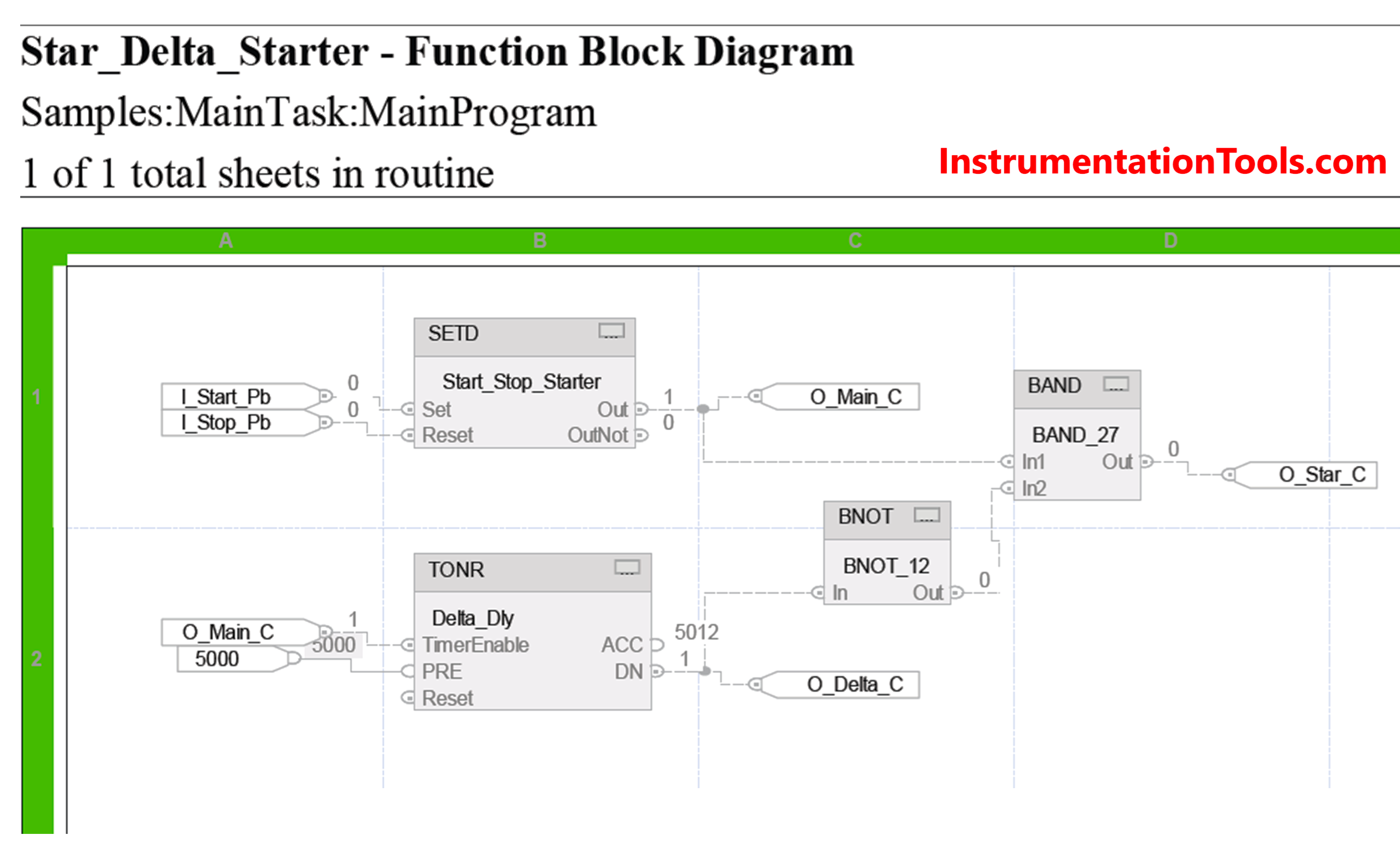
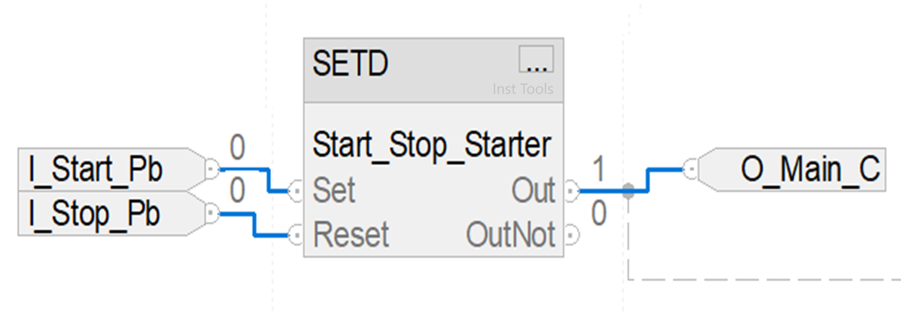
Refer to the below image. We will first turn on the main contactor (shown in blue lines). We use the SETD block here. In this block, there are two inputs – set and reset. If the set bit is high, then the output is set. If the reset bit is high, then the output is reset, on the condition that the set input is not high.
It means set input is given priority over reset input. So, when the start button is pressed, the output turns on. When the stop button is pressed, the output turns off. All the outputs turn off as they all are linked with this single output.
Once the main contactor is on, we turn the star contactor on (shown in blue lines). Refer to the below image. It turns on when the main contactor is on and the timer of 5 seconds has not elapsed. Once the timer elapses, the output will turn off.
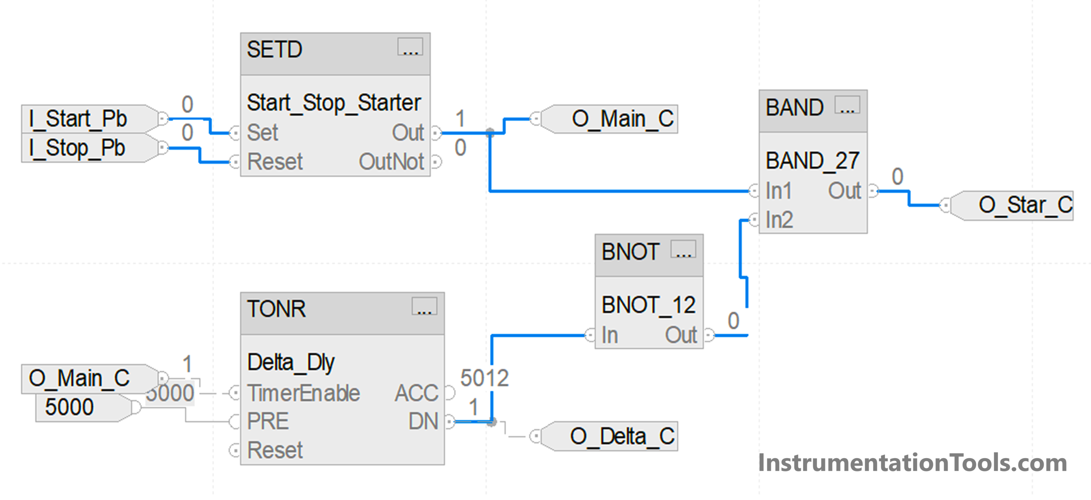
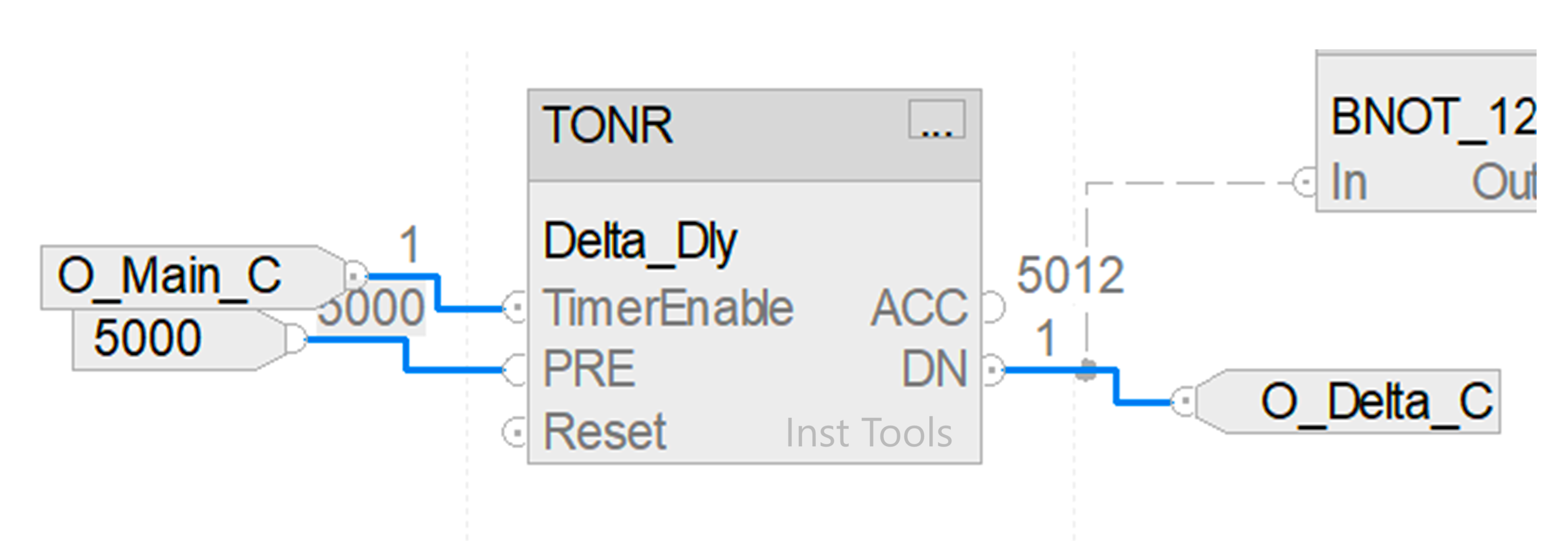
Once the main contactor is on, we also turn the timer on for the delta contactor (shown in blue lines). Refer to the below image. It turns on when the main contactor is on and the timer of 5 seconds has elapsed. Once the timer elapses, the output will turn on.
In this way, we saw how to write a PLC program for star delta starters using a functional block diagram.
Read Next:
- Star Delta Starter Circuit, Advantages, Disadvantages
- Delta HMI and VFD Control with Modbus
- Difference between Soft Starter and VFD
- How to Run Multiple Motors with a Single VFD?
- VFD Engineer Roles – Installation and Commissioning