Inst ToolsInst ToolsInst Tools
  • Courses
  • Automation
    • PLC
    • Control System
    • Safety System
    • Communication
    • Fire & Gas System
  • Instrumentation
    • Design
    • Pressure
    • Temperature
    • Flow
    • Level
    • Vibration
    • Analyzer
    • Control Valve
    • Switch
    • Calibration
    • Erection & Commissioning
  • Interview
    • Instrumentation
    • Electrical
    • Electronics
    • Practical
  • Q&A
    • Instrumentation
    • Control System
    • Electrical
    • Electronics
    • Analog Electronics
    • Digital Electronics
    • Power Electronics
    • Microprocessor
  • Request
Search
  • Books
  • Software
  • Projects
  • Process
  • Tools
  • Basics
  • Formula
  • Power Plant
  • Root Cause Analysis
  • Electrical Basics
  • Animation
  • Standards
  • 4-20 mA Course
  • Siemens PLC Course
Reading: Structured Text PLC Program for Measuring Event Duration
Share
Font ResizerAa
Inst ToolsInst Tools
Font ResizerAa
  • Courses
  • Design
  • PLC
  • Interview
  • Control System
Search
  • Courses
  • Automation
    • PLC
    • Control System
    • Safety System
    • Communication
    • Fire & Gas System
  • Instrumentation
    • Design
    • Pressure
    • Temperature
    • Flow
    • Level
    • Vibration
    • Analyzer
    • Control Valve
    • Switch
    • Calibration
    • Erection & Commissioning
  • Interview
    • Instrumentation
    • Electrical
    • Electronics
    • Practical
  • Q&A
    • Instrumentation
    • Control System
    • Electrical
    • Electronics
    • Analog Electronics
    • Digital Electronics
    • Power Electronics
    • Microprocessor
  • Request
Follow US
All rights reserved. Reproduction in whole or in part without written permission is prohibited.
Inst Tools > Blog > PLC Tutorials > Structured Text PLC Program for Measuring Event Duration

Structured Text PLC Program for Measuring Event Duration

Learn how to create a Structured Text PLC program to measure the time taken by an event between two sensors.

Last updated: September 13, 2024 3:05 pm
Viral Nagda
PLC Tutorials
No Comments
Share
5 Min Read
SHARE

In industrial automation, there arises an occasion where you are required to measure the time taken for a particular event and show it to the operator. This helps in realizing how a process is working and how much time it is taking.

Contents
PLC Program for Measuring Event DurationStructured Text PLC Program

Troubleshooting improves a lot due to this logic. In PLC programming, structured text is a language which is used in many applications for high-level troubleshooting and ease of writing. In this post, we will learn how to write a PLC program for measuring the time taken by an event using structured text.

PLC Program for Measuring Event Duration

Let us understand the case scenario first. There are two sensors on a conveyor, one mounted on the left and the other on the right.

When an object passes the first sensor, it means the timer should start to count. When that object passes the second sensor, it means the timer should stop to count, as the object has passed now. The time taken to travel from sensor-1 to sensor-2 is the event to be measured.

Structured Text PLC Program

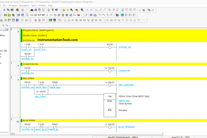
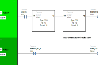
Now, let us write the PLC program. Refer to the below image. There are only two PLC digital inputs – sensor-1 and sensor-2.

Structured Text PLC Program for Measuring Event Duration

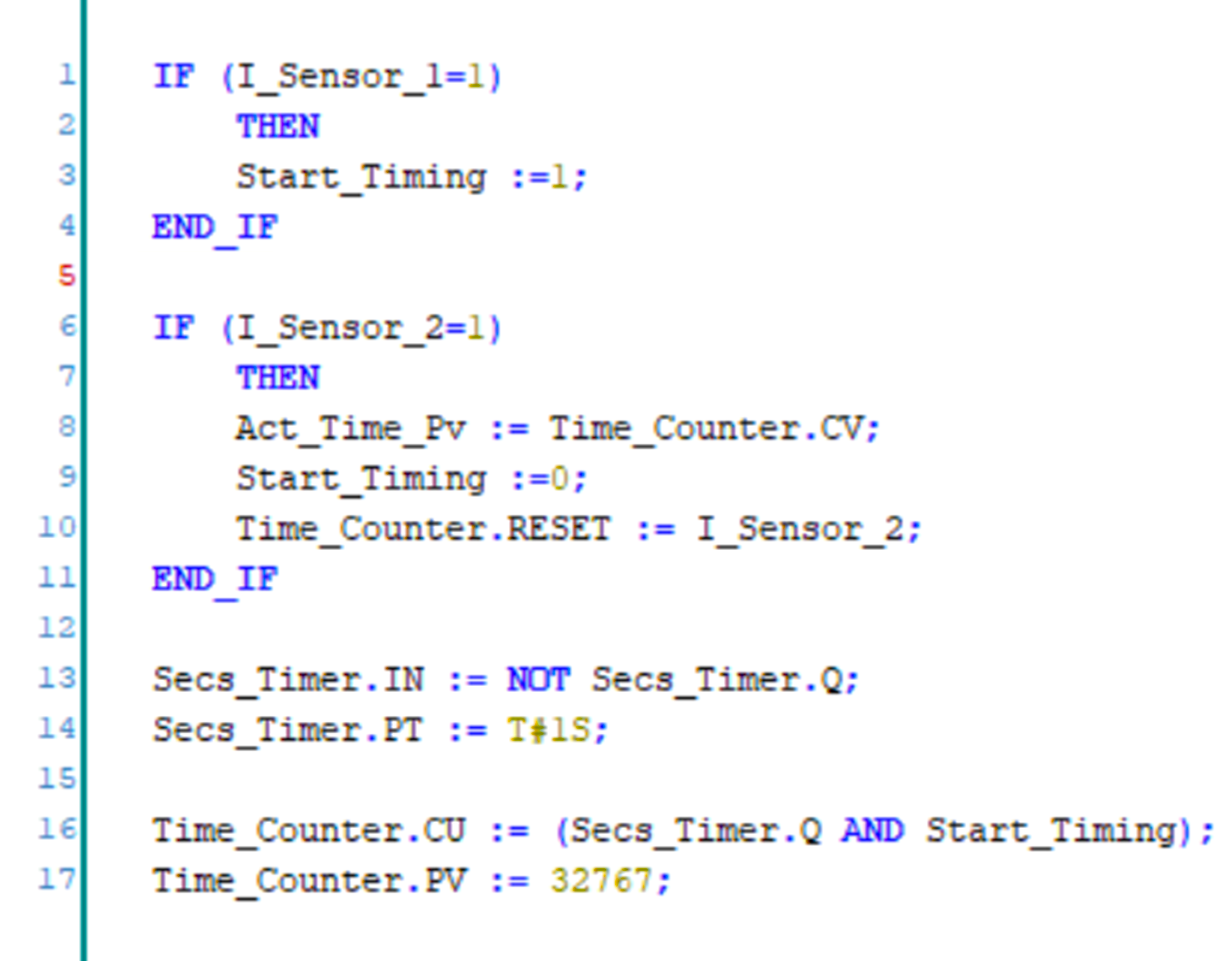
When sensor-1 is sensed, we set a bit named Start_Timing by moving value 1. We will now require two elements – one timer for giving one second pulse and one counter for counting the time traveled. The timer will give one second pulse to the counter, so that it can count the timing in seconds.

For this, we first write the timer logic in the third part as shown. The timer input will be the negate of the timer done bit. The timer set value will be 1 second. Due to this, the timer will continuously be on and off for every 1 second. We can then use it’s output for our next part.

In the fourth part, we write the counter logic. The counter input will be the done bit of the timer and start_timing bit. Means, the counter will start counting only when this bit is set first.

The counter set value will be 32767 (based on our conveyor design which will not go beyond this much time as per sensor positioning). It means as per our design example, the travel time will not be more than 32767 seconds. As long as the bit is set, the counter will increment every second.

Now, coming to our most important part of counting the counter value. As you can see, we have written this part in the second block, above timer and counter logic. When sensor-2 is sensed, we reset the bit of Start_Timing by moving value 0.

But before that, we move the counter current value in the register where we show the accumulated value. This is because if this line is written afterward, then the counter would have been reset already and we will not get the value. So, in the third line, we reset the counter at last by sensor-2. So, the sequence goes as – first we move accumulated value, then stop counting, and then reset counting.

As sensor-2 will come in a pulse, the counter accumulated value will be holded in the register and not become zero. Due to this, the operator can every time view the last traveled time.

It is thus important to note that the sequence of lines is written properly for timely execution. Any mistake in ordering cannot run the logic properly.

In this way, we saw how to write a PLC program for measuring the time taken by an event using structured text,

Read Next:

  • Traffic Lights Ladder Diagram using Timers
  • PLC Programming With a Move Instructions
  • PID Controllers in Closed Loop Control Systems
  • Motion Detection based Street Light PLC Logic
  • PLC Programming for Pumping and Draining System

Don't Miss Our Updates
Be the first to get exclusive content straight to your email.
We promise not to spam you. You can unsubscribe at any time.
Invalid email address
You've successfully subscribed !

Continue Reading

Quiz Program Logic Using PLC Programming
Developing PLC Logic for Water Pumping and Chemical Addition
Automatic Box Filling System using PLC Programming
3 Phase Motor Control using PLC Ladder Logic
Electrical Cabinet Air Conditioner – Enclosure Cooling, Maintenance
PLC Counter Instructions
Share This Article
Facebook Whatsapp Whatsapp LinkedIn Copy Link
Share
Leave a Comment

Leave a Reply Cancel reply

Your email address will not be published. Required fields are marked *

Stay Connected

128.3kFollowersLike
69.1kFollowersFollow
210kSubscribersSubscribe
38kFollowersFollow

Categories

Explore More

SCADA Communication and Protocols
Examples of PLC Programming using Boolean Functions
PLC Program – Controls Conveyors ON and OFF Sequence
Difference between Compact PLC and Modular PLC
Structured Text PLC Example for Motor Interlocking and Control
PLC Program for Ceramic Burning Oven Conveyor System
What is a Surge Protection Device? – Principle, Types, Advantages
Extended Timer Logic in PLC

Keep Learning

Basics of Motion Controllers

Basics of Motion Controllers

PLC Programming Example on Timers Function Block

PLC Programming Example on Timers Function Block

Introduction to Schneider PLC

Different Types of Schneider PLC

PLC Program to Energize & De-energize the Outputs based on Events

PLC Energize or De-energize the Outputs based on Events

Field Instruments

#11 PLC Best Practices – Instrument for Plausibility Checks

S7-1200 Hardware Configuration

S7-1200 Hardware Configuration – Siemens PLC Tutorials

PLC Program using Logic GATEs

PLC Logic GATE Program

PLC Hoist Crane Programming

PLC Hoist Crane Programming: Example using Schneider

Learn More

Questions & Answers of Power Systems

Questions & Answers of Power Systems

RFID Technology in Industrial Automation

RFID Technology in Industrial Automation

fundamentals of an AC motor

How does an Electric Motor Operate? – AC Motor Fundamentals

As-Interface Protocol Overview

AS-interface and DeviceNet Communication

pressurized water reactor

SIS Example : Nuclear Reactor Controls

Pneumatic-Level-Transmitter-Value-Struck

Pneumatic Level Transmitter Value Struck?

Limit, Selector, and Override controls

Limit, Selector, and Override controls

Preventive Maintenance of Variable Frequency Drive

Preventive Maintenance of Variable Frequency Drive (VFD)

Menu

  • About
  • Privacy Policy
  • Copyright

Quick Links

  • Learn PLC
  • Helping Hand
  • Part Time Job

YouTube Subscribe

Follow US
All rights reserved. Reproduction in whole or in part without written permission is prohibited.
Welcome Back!

Sign in to your account

Username or Email Address
Password

Lost your password?