Inst ToolsInst ToolsInst Tools
  • Ask
  • Courses
  • Videos
  • Q & A
    • Interview
      • Instrumentation
      • Electronics
      • Electrical
      • Practical Questions
    • MCQ
      • Instrumentation MCQ
      • Electrical MCQ
      • Electronics MCQ
      • Control Systems MCQ
      • Analog Electronics MCQ
      • Digital Electronics MCQ
      • Power Electronics MCQ
      • Microprocessor MCQ
      • Multiple Choice Questions
  • EE
    • Electronics
      • Electronics Q & A
      • Electronic Basics
      • Electronic Devices & Circuits
      • Electronics Animation
      • Digital Electronics
    • Electrical
      • Electrical Basics
      • Electrical Q & A
      • Power Electronics
      • Electrical Machines
      • Electrical Animation
      • Power Systems
      • Switchgear & Protection
      • Transmission & Distribution
  • Measure
    • Control Valves
    • Calibration
    • Temperature
    • Pressure
    • Flow
    • Level
    • Analyzers
    • Switches
    • Vibration
    • Solenoid Valve
  • Control
    • PLC Tutorials
    • Control Systems
    • Safety Instrumented System (SIS)
    • Communication
    • Fire & Gas System
  • More
    • Design
    • Tools
    • Animation
    • Basics
    • Formulas
    • Standards
    • TextBooks
    • Common
    • Software
    • Excel Tools
    • Erection & Commissioning
    • Process Fundamentals
    • Videos
    • Books
Search
All rights reserved. Reproduction in whole or in part without written permission is prohibited.
Reading: PLC Program for Mailbox with Letter Counting & Light Indicators
Share
Notification Show More
Font ResizerAa
Inst ToolsInst Tools
Font ResizerAa
  • Courses
  • PLC Tutorials
  • Control Systems
Search
  • Ask
  • Courses
  • Videos
  • Q & A
    • Interview
    • MCQ
  • EE
    • Electronics
    • Electrical
  • Measure
    • Control Valves
    • Calibration
    • Temperature
    • Pressure
    • Flow
    • Level
    • Analyzers
    • Switches
    • Vibration
    • Solenoid Valve
  • Control
    • PLC Tutorials
    • Control Systems
    • Safety Instrumented System (SIS)
    • Communication
    • Fire & Gas System
  • More
    • Design
    • Tools
    • Animation
    • Basics
    • Formulas
    • Standards
    • TextBooks
    • Common
    • Software
    • Excel Tools
    • Erection & Commissioning
    • Process Fundamentals
    • Videos
    • Books
Follow US
All rights reserved. Reproduction in whole or in part without written permission is prohibited.
Inst Tools > Blog > PLC Tutorials > PLC Program for Mailbox with Letter Counting & Light Indicators

PLC Program for Mailbox with Letter Counting & Light Indicators

Learn the step-by-step PLC program for the mailbox with letter counting and light indicators to automate real-time notifications.

Last updated: September 30, 2024 2:45 pm
Editorial Staff
PLC Tutorials
No Comments
Share
6 Min Read
SHARE

This article discusses the Mailbox Program with Counter and Light Indicator functions. The Mailbox system has a hole for inserting letters and a door which is used to take letters. This mailbox is equipped with sensors to detect incoming mail and taken mail. The mailbox will count the number of incoming letters and it will Reset the data when the letters are taken. Indicator lights (Green, Yellow, Red) are used to indicate the status of the mailbox.

Contents
Program ObjectivePLC Inputs and Outputs AddressingPLC Program for Mailbox

Program Objective

Process:

When the incoming mail sensor SENS_IN (0.02) is Active, then the program will:

  1. Increase the counter COUNT_MAIL (D0) value for the number of letters.
  2. Check the COUNT_MAIL (D0) counter value.
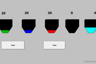
  3. If the COUNT_MAIL (D0) counter value is Not Equal to “0”, the GREEN_LAMP (100.00) indicator lamp will be ON.
  4. If the COUNT_MAIL (D0) counter value is Greater Than Or Equal to “5”, the YELLOW_LAMP (100.01) indicator lamp will turn ON and the GREEN_LAMP (100.00) indicator lamp will turn OFF.
  5. If the COUNT_MAIL (D0) counter value is Equal To “10”, the RED_LAMP (100.02) indicator lamp will turn ON and the YELLOW_LAMP (100.01) indicator lamp will turn OFF.

When the mail retrieval door sensor SENS_OUT (0.03) is Active, then the program will do the following things:

  • Reset the COUNT_MAIL (D0) counter value to “0”.
  • Turn OFF all indicator lamps.
PLC Program for Mail Box with Letter Counting and Light Indicators

PLC Inputs and Outputs Addressing

CommentInput (I)Output (Q)Memory WordMemory BitsTimer
PB_START0.00    
PB_STOP0.01    
SENS_IN0.02    
SENS_OUT0.03    
GREEN_LAMP 100.00   
YELLOW_LAMP 100.01   
RED_LAMP 100.02   
COUNT_MAIL  D0  
SYSTEM_ON   W0.00 
IR_YELLOW_LAMP   W0.01 
IR_RED_LAMP   W0.02 

PLC Program for Mailbox

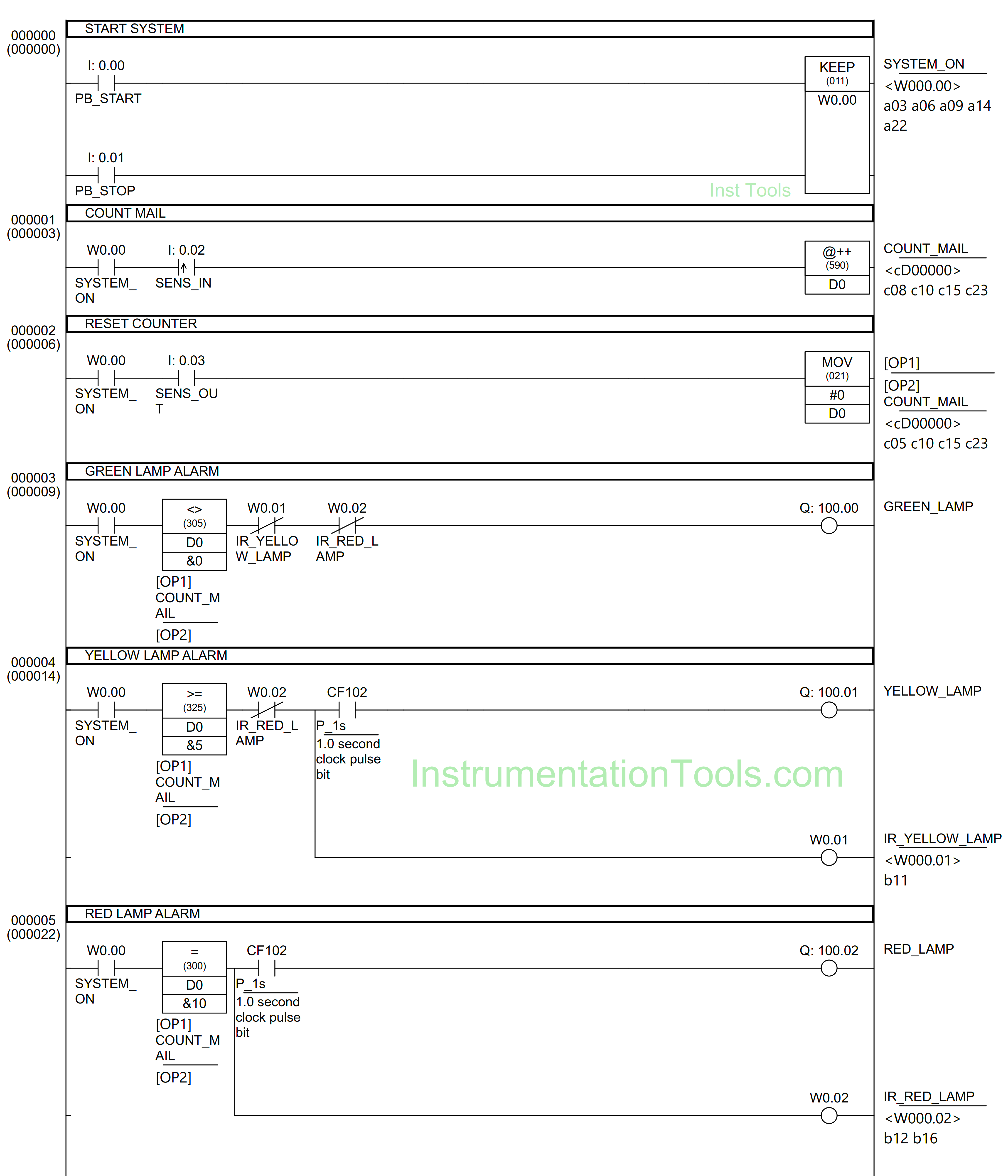
RUNG 0 (START SYSTEM)

In this Rung, when the PB_START (0.00) button is pressed, the memory bit SYSTEM_ON (W0.00) will be in the HIGH state. Because the KEEP(011) instruction is used, the memory bit SYSTEM_ON (W0.00) remains in the HIGH state even though the PB_START (0.00) button has been Released.

The memory bit SYSTEM_ON (W0.00) will become a LOW state if the PB_STOP (0.01) button is Pressed.
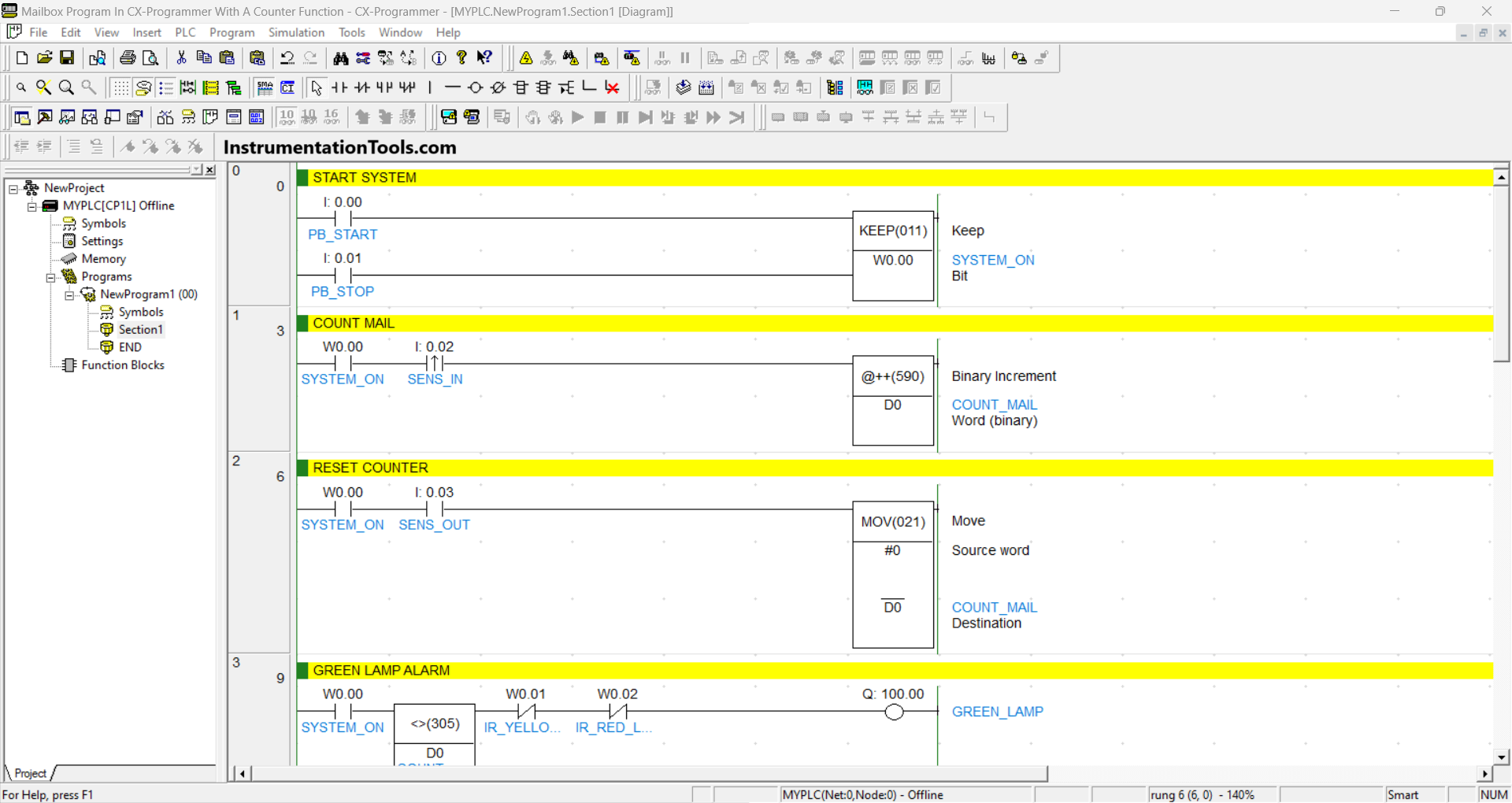
PLC-based mail box automation

RUNG 1 (COUNT MAIL)

In this Rung, when the NO contact of memory bit SYSTEM_ON (W0.00) and Sensor SENS_IN (0.02) in the HIGH state, the value in memory word COUNT_MAIL (D0) will increase (+1), because it uses the Binary Increment @++(590) Instruction.

RUNG 2 (RESET COUNTER)

In this Rung, when the NO contact of memory bit SYSTEM_ON (W0.00) and the Sensor SENS_OUT (0.03) in HIGH state, the value in memory word COUNT_MAIL (D0) will be Reset to zero “0”. Because the MOV(021) instruction moves the zero value “0” to the memory word COUNT_MAIL (D0).

Mail box letter detection

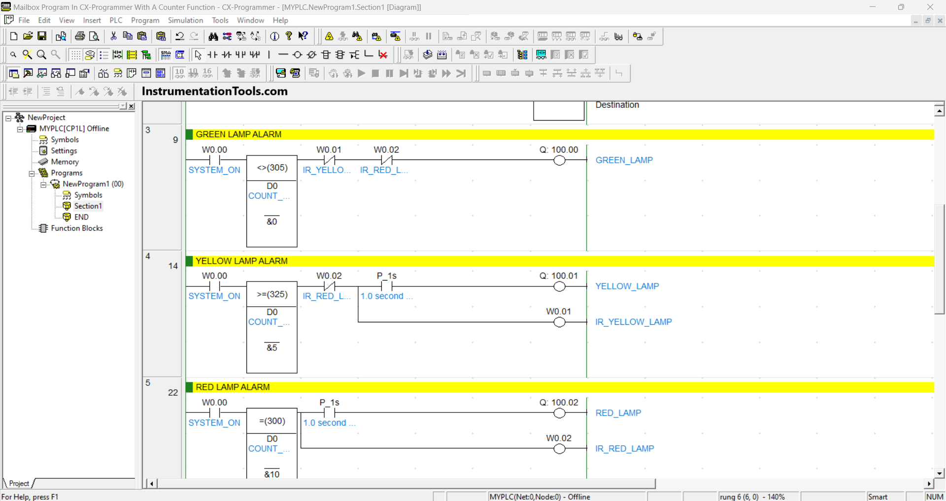
RUNG 3 (GREEN LAMP ALARM)

In this Rung, when the NO contact of memory bit SYSTEM_ON (W0.00) and the value in memory word COUNT_MAIL (D0) are Not Equal to “0”, then the Output GREEN_LAMP (100.00) will be ON.

The GREEN_LAMP (100.00) output will be OFF if the NC contacts of memory bit IR_YELLOW_LAMP (W0.01) and IR_RED_LAMP (W0.02) are in the HIGH state.

RUNG 4 (YELLOW LAMP ALARM)

In this Rung, when the NO contact of memory bit SYSTEM_ON (W0.00) and the value in memory word COUNT_MAIL (D0) is Greater Than Or Equal to “5”, then the Output YELLOW_LAMP (100.01) will be ON and the memory bit IR_YELLOW_LAMP (W0.01 ) will be in the HIGH state.

Output YELLOW_LAMP (100.01) will be ON blinking with an interval of 1 second, because the NO contact of P_1s (1.0 second clock pulse bit).

The YELLOW_LAMP (100.01) output will be OFF if the NC contact of memory bit IR_RED_LAMP (W0.02) in the HIGH state.

Letter counter PLC program

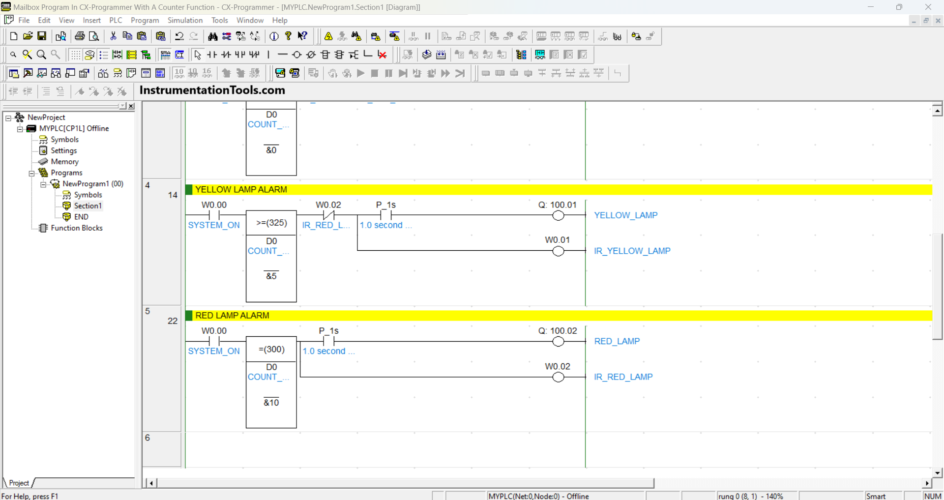
RUNG 5 (RED LAMP ALARM)

In this Rung, when the NO contact of memory bit SYSTEM_ON (W0.00) and the value in memory word COUNT_MAIL (D0) is Equal to “10”, then the Output RED_LAMP (100.02) will be ON and the memory bit IR_RED_LAMP (W0.02) will be in HIGH state.

The RED_LAMP (100.02) output will be ON blinking with an interval of 1 second because of the NO contact of P_1s (1.0 second clock pulse bit).

Read Next:

  • Medium-Level PLC Exercise for Students
  • Dosing Pump PLC Programming Logic
  • PLC Programming based on Logic Circuit
  • Schneider Electric PLC Timer Problems
  • PLC Programming 3 Motors with Priority
Don't Miss Our Updates
Be the first to get exclusive content straight to your email.
We promise not to spam you. You can unsubscribe at any time.
Invalid email address
You've successfully subscribed !
PLC Controlled Conveyor and Weighing with Labeling Automation
Control Room and Field Instruments Questions and Answers
Motor Control Circuits
Classroom Bell System – PLC Programming Practice Examples
Rockwell PLCs for Large Scale Applications
Share This Article
Facebook Whatsapp Whatsapp LinkedIn Copy Link
Share
Leave a Comment

Leave a Reply Cancel reply

Your email address will not be published. Required fields are marked *

Stay Connected

128.3kFollowersLike
69.1kFollowersFollow
208kSubscribersSubscribe
38kFollowersFollow

Categories

Recent Comments

  • Kamli on Top Free PLC Software
  • Guifty Shimica on Top Non-PLC Certification Courses for Automation Professionals
  • Guifty Shimica on Top Non-PLC Certification Courses for Automation Professionals
  • MIHARITSOA Aina Sitraka on Top Non-PLC Certification Courses for Automation Professionals

Related Articles

Example Program Logic in Allen Bradley PLC

PLC Programming Examples on Industrial Automation

Function Block Diagram - Studio 5000 Logix Designer

Define the Order of Execution in Functional Block Diagram of Studio 5000

Electrical and Instrumentation Engineering Documents

Electrical and Instrumentation – Automation Pre-engineering Documents

Reading Clock data in PLC

Real-Time Clock in Omron PLC? – CX Programmer

Track PLC Operating Modes

#2 PLC Best Practices – Track Operating Modes

Analog Inputs in Siemens TIA Portal

What are Analog Inputs? – Analog Signals Processing in PLC

SCADA Run

PLC Based Industrial Conveyor Ladder Logic

car parking example logic

Up Down Counter Instruction in PLC

More Articles

Pressure Control Loop

Pressure Control Loop Wiring Connections

Power Electronics Objective Questions

1 Phase Voltage Source Inverter Quiz

Multiple Thermowell Installations Problems

Multiple Thermowell Installations Problems

Types of Batteries

Cells and Batteries – Types, Applications, Explanation

Voltage Control & Circuit Breakers Interview Questions

Voltage Control & Circuit Breakers Interview Questions

Flow Measurement Questions

MCQ on Flow Measurement

Siemens Process Mode

Test and Process Modes in Siemens PLC

PID-Controller-Selection

PID Controller Selection

Follow US
All rights reserved. Reproduction in whole or in part without written permission is prohibited.
Welcome Back!

Sign in to your account

Username or Email Address
Password

Lost your password?