This is the PLC Program for Conditional Logic Circuit. The below example is based on the ladder logic using a programmable logic controller.
In Industry or plants, there are lots of gearbox systems used for different machines/motors.
For smooth operation of gearbox motors, they need to be lubricated every time because good maintenance work can extend gearbox life.
But the problem is that operators often make mistakes during machine operation because in every gearbox motor mechanism, we need to start lubrication first and then the main gearbox mechanism should start.
So we have to implement a logic to make sure things are properly controlled from a PLC system.
Note: For easy discussions, Local/Remote, or any other permissive interlocks are not considered in this example.
Here we solve this problem by using a simple conditional logic example, in this example, there is one gearbox motor and we need to provide lubrication before starting it.
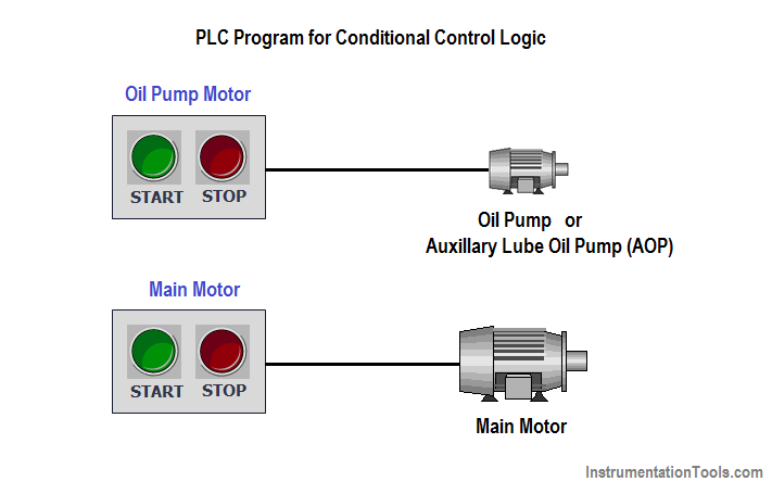
So for lubrication, we have a lubrication motor (also called as Oil Pump or Auxiliary Lube Oil Pump) and it will provide lubrication oil to the main motor or gearbox motor.
Also, we will provide an interlock system, so the operator cannot start/operate the Main motor directly without using proper lubrication otherwise the main motor may overheat and it may be damaged after some runs without proper care.
The operator has to switch ON oil pump first and then only he can able to operate the main motor.
By using this logic, we can take care of the gearbox motor for a long time run with proper lubrication.
Operators start/stop oil pump by using START and STOP push buttons of oil pump.
Both Oil Pump and Main Motor have separate individual START & STOP push buttons as shown in above diagram.
Note: The above PLC Logic provided for basic idea about application of PLC Program for Conditional Control Logic. The Logic is limited and not complete application.
If you liked this article, then please subscribe to our YouTube Channel for PLC and SCADA video tutorials.
You can also follow us on Facebook and Twitter to receive daily updates.
Read Next:
The conveyor sorting machine is widely used in the packing industries using the PLC program…
Learn the example of flip-flop PLC program for lamps application using the ladder logic to…
In this article, you will learn the STAR DELTA programming using PLC controller to start…
Lube oil consoles of rotary equipment packages in industrial process plants are usually equipped with…
Rotating equipment packages such as pumps, compressors, turbines need the lube oil consoles for their…
This article explains how to blink lights in ladder logic with a detailed explanation video…


View Comments
Dear Sir,
This is not foolproof logic.This is just a interlock with lot of loop holes.
Hi Sharma, I think the Author just explaining a simple example of conditional logic, not designing complete application/logic. Can You please share the loop holes, Thanks.
Dear Sir,
Sorry for inconvenience
This is example for concept explanation of conditional circuit.
It is not complete system.
Simple but effective circuit for easy understanding... Thanxs to you. Bhavesh sir, please share more plc. Logic