Here we discuss about PLC Pneumatic Circuit Control with different examples. PLC ladder diagram for single-acting and double-acting pneumatic cylinders.
PLC Pneumatic Circuit Examples
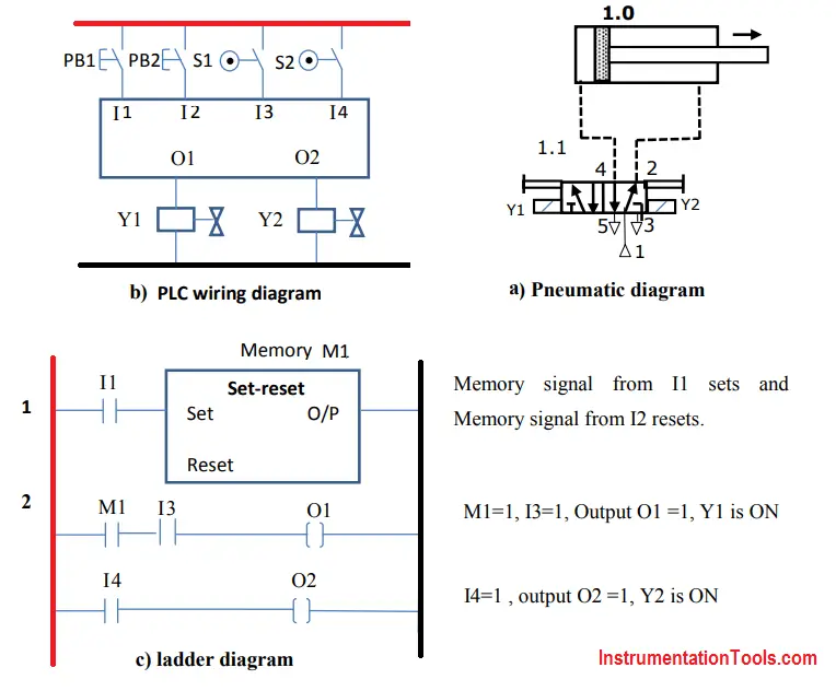
Example 1 :
A double-acting cylinder is used to perform machinng operation. Pneumatic cylinder is advanced by pressing two push buttons simultaneously. If any one of the push button is released, cylinder comes back to start position. Draw the pneumatic circuit, PLC wiring diagram and ladder diagram to implement this task.
Solution :
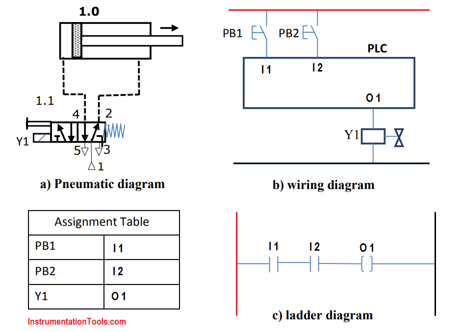
As shown in the PLC wiring diaram, The push buttons PB1 and PB2 are connected at memory address I1 and I2.
I1 and I2 are connected in series in ladder diagram to realize this AND logic function.
When the push buttons PB1 and PB2 are pressed simultaneously, the addresses I1 and I 2 turn to state 1 from state 0 , as a result power flows through the coil and there will be output at coil 01. Output at the coil 01 operated the solenoid coil and cylinder moves forward to do the required operation.
If any one of PB1 and PB2 is pressed, then corresponding bit addresses turns to 0, since I1 and I2 are in series , if any of them turns to 0 state , there will not be any output at 01 and thus solenoid is de-energised and returns back.
Example 2 :
Double acting cylinder is used to perform forward and return motion. Pneumatic cylinder is advanced by pressing push buttons PB1. Cylinder is returned by pressing push button PB2. Draw the pneumatic circuit, PLC wiring diagram and ladder diagram to implement this task.
Solution
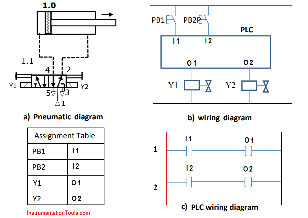
PLC Wiring diagram and Ladder diagrams are shown in above Figure. when the push button PB1 is pressed state of the address I1 turns to 1 and thus there will be output 01. The output of 01 operates the solenoid Y1 and cylinder moves forward,
When the cylinder reaches the extreme forward position, and Push button PB2 is operated , the state of address I2 turns to 1 and thus there will be output 02. The output of 02 operates the solenoid Y2 and cylinder return back to initial position.
Example 3 :
Double acting cylinder is used to perform forward and return automatically after reaching the extreme forward position. Pneumatic cylinder is advanced by pressing push buttons PB1. Draw the pneumatic circuit, PLC wiring diagram and ladder diagram to implement this task.
Solution
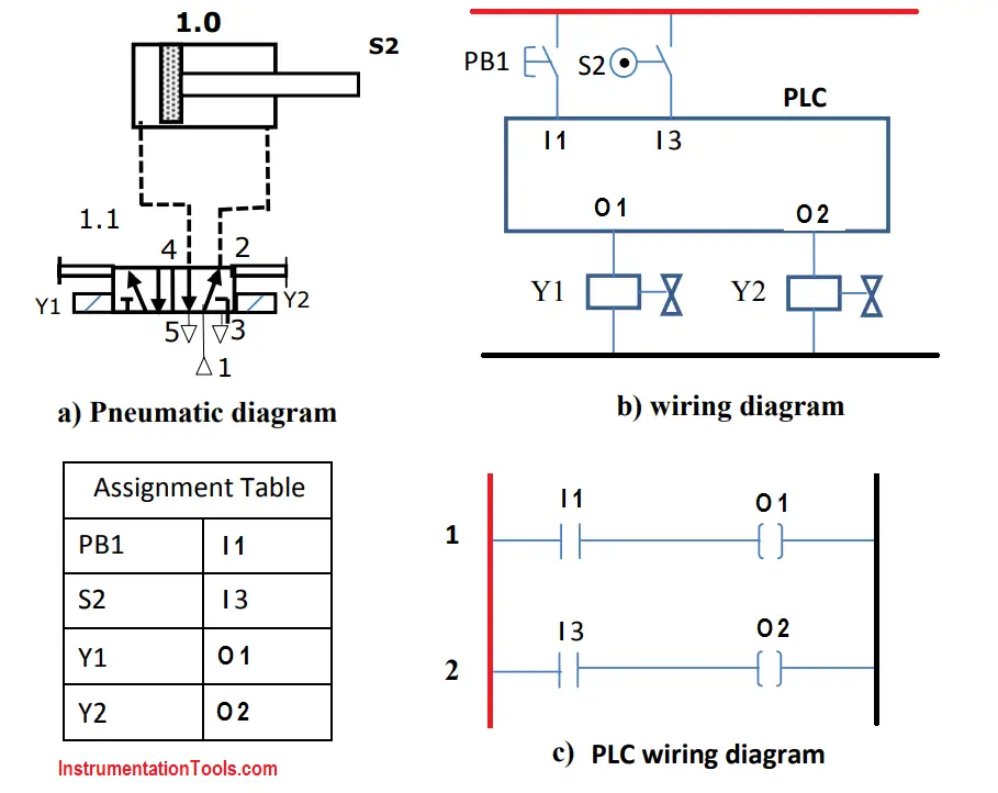
PLC Wiring diagram and Ladder diagrams are shown in above Figure. when the pushbutton PB1 is pressed state of the address I1 turns to 1 and thus there will be output 01. The output of 01 operates the solenoid Y1 and cylinder moves forward.
When the cylinder reaches the extreme forward position, and Limit switch S2 is operated , the state of address I3 turns to 1 and thus there will be output 02. The output of 02 operates the solenoid Y2 and cylinder return back to initial position.
Example 4 :
Double acting cylinder is used to perform pressing operation. Cylinder has to move forward when PB1 button is pressed and return for set time of 20 seconds before it automatically returns to intial position. Limit switch S2 is used for end sensing of the forward motion of the cylinder. Draw the pneumatic circuit, PLC wiring diagram and ladder diagram to implement this task.
Solution
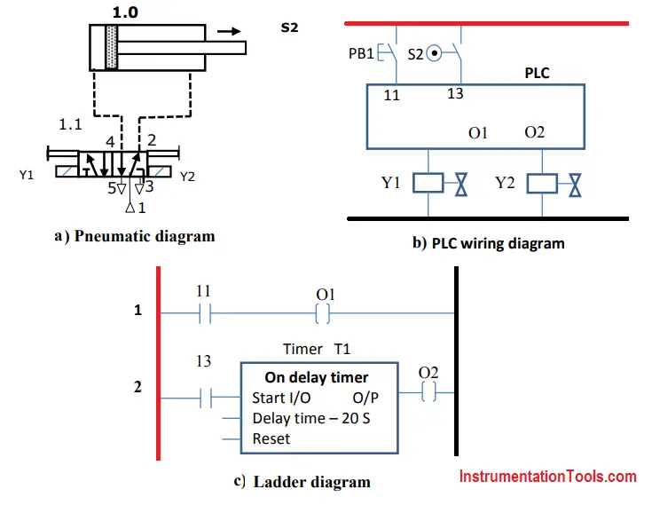
When PB1 is pressed, address I1 input state goes to 1 and there is an output at O1. Due to output at O1, the solenoid coil Y1 is operated and cylinder moves forward.
When cylinder reaches end position, limit switch S2 is operated and as a result address I3 changes to 1 and consequently starts the timer T1.
The signal state of timer T1 changes to 1 after 20 seconds is reached. At the end of 20 seconds there will be output from Timer T1 set output O2. Coil Y2 is energised thus causing the return motion of the cylinder.
Example 5 :
Double acting cylinder is used to perform continuous to and fro motion. Cylinder has to move forward when PB1 button is pressed and once to and fro reciprocation starts it should continue till stop button PB2 is pressed. Limit swithces are used for end position sensing. Draw the pneumatic circuit, PLC wiring diagram and ladder diagram to implement this task.
Solution :
The start and stop operations can be implemented using memory flag with address M1 that is set by PB1 and reset by PB2.
The state of the memory element M1 is scanned through an NO contact, is combined in series with the state of sensor S1 to get start and stop controls.
Example 6 :
Double acting cylinder is used to perform to and fro operation. Cylinder has to move forward when PB1 button is pressed and continue to and fro motion till 10 cycles of operations is performed. Draw the pneumatic circuit, PLC wiring diagram and ladder diagram to implement this task.
Solution
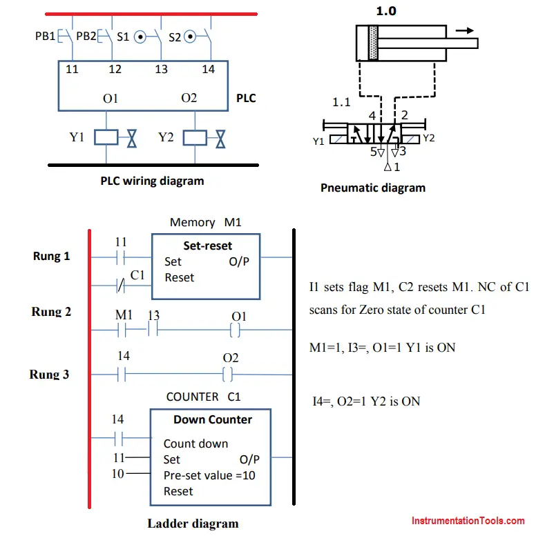
The fully automatic operation of cylinder can be obtained as earlier using limit switch S1 and S2.
Start and stop operation can be implemented using memory flag with address M1 that is set by PB1 at I1 and reset by NC contact of a down counter.
The state of memory flag M1 scanned through an NO contact (rung 2) is combined in series with the state sensor S1 to get start and stop controls.
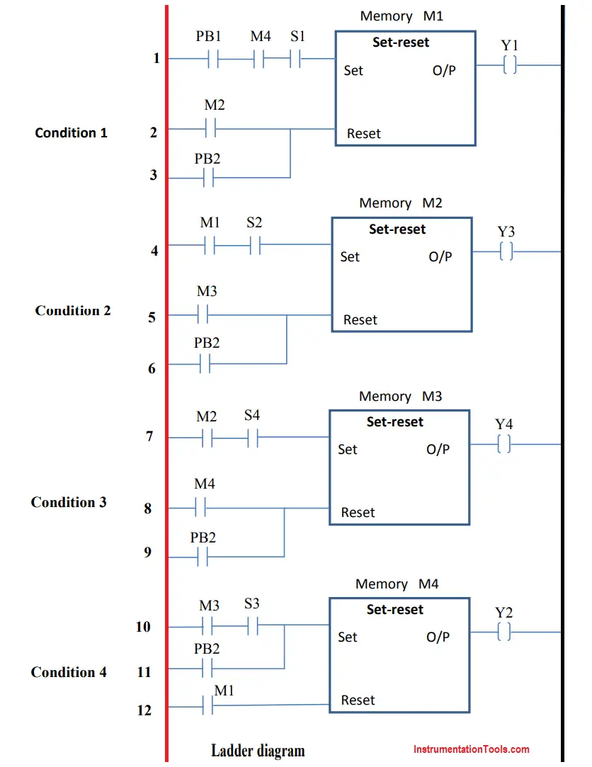
Example 7 :
Draw the pneumatic circuit, PLC wiring diagram and ladder diagram to implement A+B+B-A- sequence.
Solution
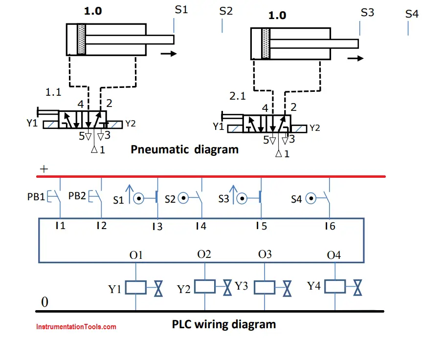
In this sequence circuit, PB2 is used to initiate the program. Pressing PB2 causes the last memory state M4 to set and all other memory flags M1, M2 and M3 to reset. Initially S1 and S3 are actuated and generate outputs.
Condition 1:
Pressing PB1 sets Memory flag M1 and resets Memory flag M4. Solenoid Y1 is energised. Cylinder A extends (A+). Sensor S1 is deactivated once A travels and S2 is activated when end position is reached.
Condition 2:
When S2 is actuated, memory M2 is set and Memory flag M1 is reset. Solenoid Y3 is energised. Cylinder B extends (B+). Sensor S3 is deactivated once B travels and S4 is activated when end position is reached.
Condition 3:
When S4 is actuated, memory M3 is set and Memory flag M2 is reset. Solenoid Y4 is energised. Cylinder B retracts (B-). Sensor S4 is deactivated once B travels and S3 is activated when initial position is reached.
Condition 4:
When S3 is actuated, memory M4 is set and Memory flag M3 is reset. Solenoid Y2 is energised. Cylinder A retracts (A-). Sensor S2 is deactivated once B travels and S1 is activated when initial position is reached.
If you liked this article, then please subscribe to our YouTube Channel for PLC and SCADA video tutorials.
You can also follow us on Facebook and Twitter to receive daily updates.
Read Next:
- Relay Schematic Animation
- PLC Program for Mixing Tank
- Counter Instructions in PLC
- Mis-conceptions of PLC Logic
- History of PLC


This is excellent. Thank you.
Very useful