Develop the PLC program to execute the operational sequence of the packaging process.
The following description explains the logic rung wise.
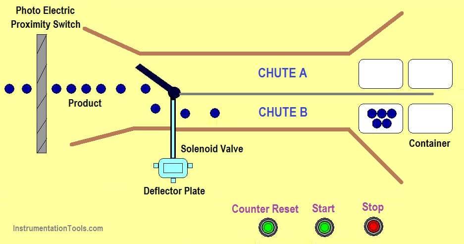
Latching rung to operate the system through Master Start (I:0/0) and Stop PB (I:0/1).
Start memory latch (B3:0/0) and proximity switch (I:0/2) are connected in series to make a count of each product crossing and chute A indicator lamp also turn ON (O:0/1)
Counter done bit enables to turn on another memory (B3:0/1) to trigger a solenoid valve to change deflector plate from chute A to chute B. Chute B indicator (O:0/2) enables.
Once 50 product entered chute B, counter done bit makes solenoid valve to go off and triggers deflector plate to favors chute A. Chute A indicator (O:0/1) is connected in a normally closed contact to break a memory latch.
Counter automatically reset when done bit enables. Manual reset (I:0/3) is connected in parallel to reset the counter manually.
The program runs continuously until STOP PB is pressed.
The above-explained operational sequence of packaging process is for example only. It may vary from real-time. We can use this example program to understand the working of timers, memory bit and interlocking concept function in AB PLC.
Author: Hema Sundaresan
If you liked this article, then please subscribe to our YouTube Channel for PLC and SCADA video tutorials.
You can also follow us on Facebook and Twitter to receive daily updates.
Read Next:
Learn the example of flip-flop PLC program for lamps application using the ladder logic to…
In this article, you will learn the STAR DELTA programming using PLC controller to start…
Lube oil consoles of rotary equipment packages in industrial process plants are usually equipped with…
Rotating equipment packages such as pumps, compressors, turbines need the lube oil consoles for their…
This article explains how to blink lights in ladder logic with a detailed explanation video…
In this article, a simple example will teach you the conversion from Boolean algebra to…


