In industrial automation, instruments play a very important role. No process can function without the installation of instruments, as they help in measuring values and feeding them to controllers for logical functioning.
Analog instruments are very important for PLC logic. When using analog instruments, we are often required to configure alarms for them according to control philosophy. In this post, we will write a PLC logic for configuring analog alarms using a functional block diagram.
PLC Logic for Analog Alarms
Let us understand the case scenario first. We have a pressure transmitter, which is analog in nature. We have two cases. In the first case, if pressure becomes high, then the system will trip after a delay. The alarm can be reset by pressing the reset button.
Before the system trip, if pressure becomes normal at any time, then the timers will reset. In the second case, if pressure becomes high, then an alarm will be generated after 5 seconds. This warning can be used to operate a safety device in the process of bringing the pressure down.
Then, this alarm will be used to further check the pressure high-high alarm. If the pressure remains high-high, then an alarm will be generated and the system will trip after 5 seconds. This alarm can be reset by either pressing the reset button or when the pressure becomes normal before the system trip timer elapses.
Functional Block Diagram
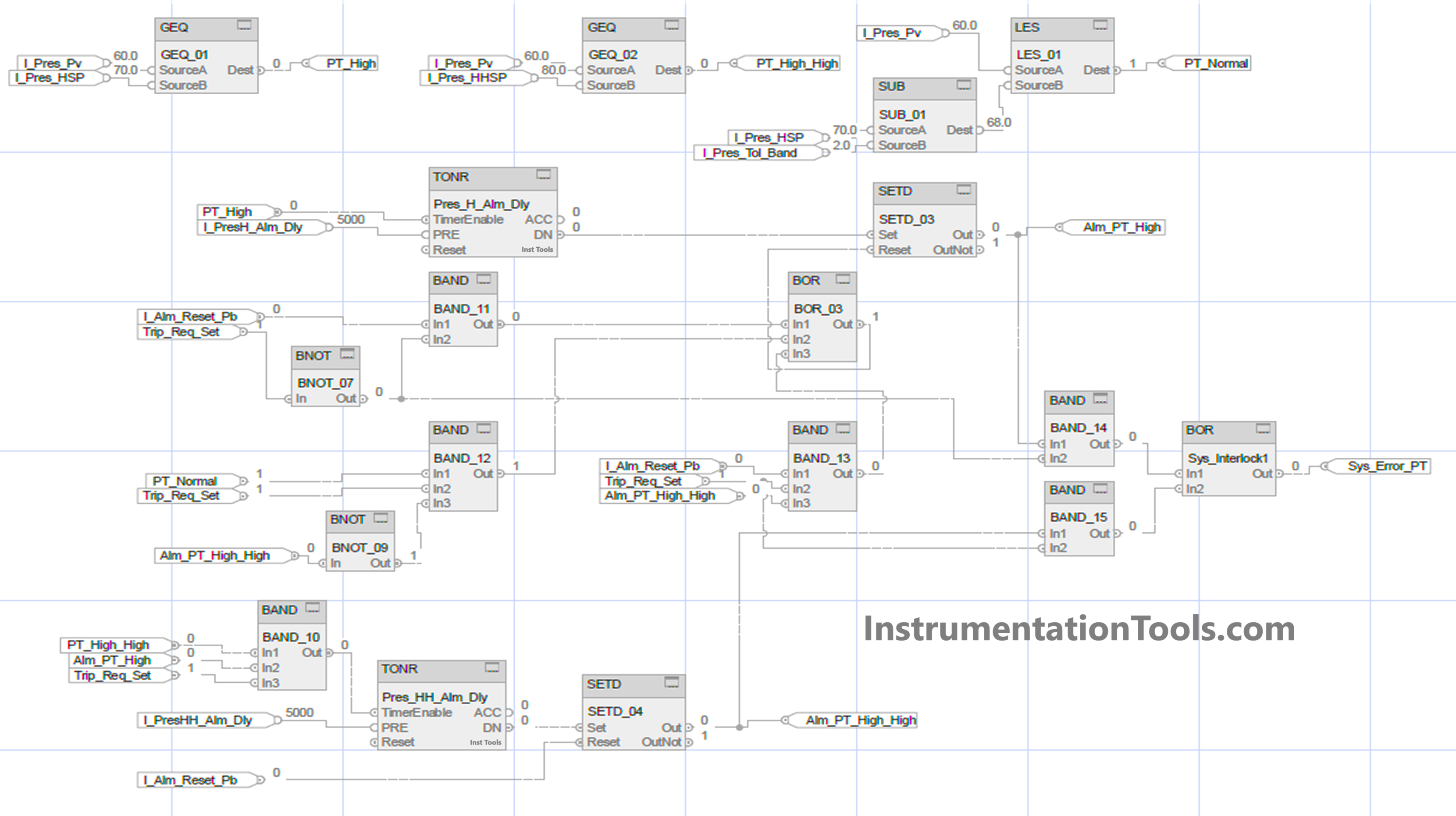
Let us write the PLC logic now. We will use functional block diagram language in the Studio 5000 platform. Refer to the below image.
These are the following input variables – pressure transmitter, pressure high alarm delay set, alarm reset push button, trip logic selection, pressure high-high alarm delay set, pressure high setpoint, pressure high-high setpoint, and pressure tolerance band.
These are the following output variables – pressure high alarm, pressure high-high alarm, and system error.
[Tolerance values must be used for analog values, to avoid fluctuations in the logic, as the analog value varies. This allows you a very stable operation and avoids constant on and off.]
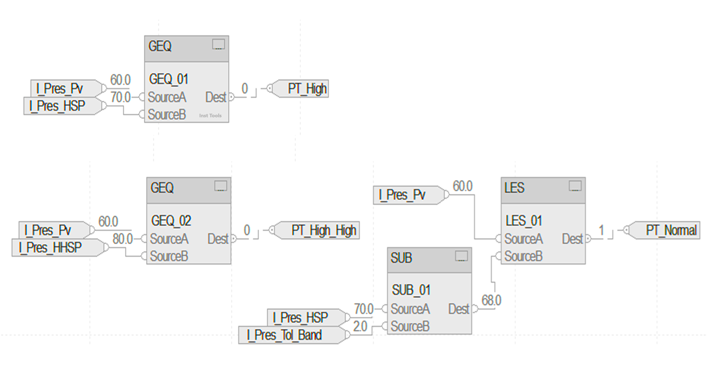
Now, we will first see how the pressure transmitter is compared with various setpoints. Refer to the below image. We are generating three conditions – pressure high, pressure high-high, and pressure normal.
Pressure high will be generated when the pressure value is more or equal to the pressure high setpoint. Pressure high-high will be generated when the pressure value is more or equal to the pressure high-high setpoint. Pressure normal will be generated when the pressure value is less than the pressure high setpoint minus the pressure tolerance band.
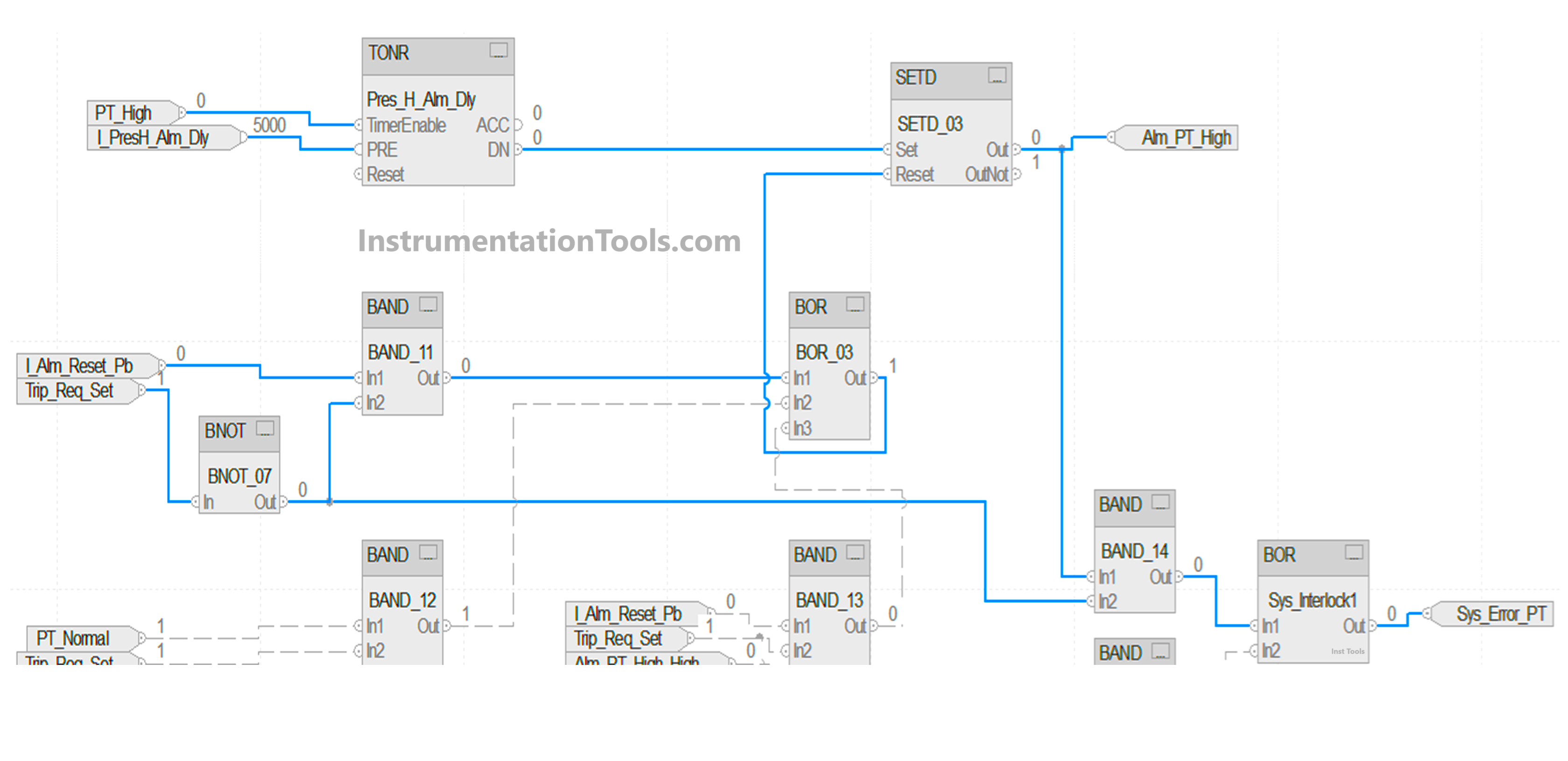
We will see the first case. Refer to the below image. The blue lines indicate the working of the first case. We use a timer for checking high pressure. It starts with the input of a pressure high for a set value of 5 seconds. If the timer is running and the pressure input goes low, then the timer is reset.
After the timer is done, the bit named alm_PT_high is set. We used the SETD block here. In this block, there are two inputs – set and reset. If the set bit is high, then the output is set. If the reset bit is high, then the output is reset, on the condition that the set input is not high.
This means that set input is given priority over reset input. For resetting the alarm, we use the AND logic of the reset button and negate trip selection. The sys_error bit is set by using the AND logic of the alarm generated and negating trip selection.
We will see the second case. Refer to the below image. The blue lines indicate the working of the second case. We will continue from the first part where the high pressure alarm bit is set.
Now, the system error will not be generated because we are using trip_req_set now as 1; which will automatically work according to our second scenario. We use a timer for checking high high pressure.
It starts with the AND logic of the pressure high-high input, alm_PT_high, and trip_req_set for a set value of 5 seconds. After the timer is done, the bit named alm_PT_high_high is set. We again used the SETD block here.
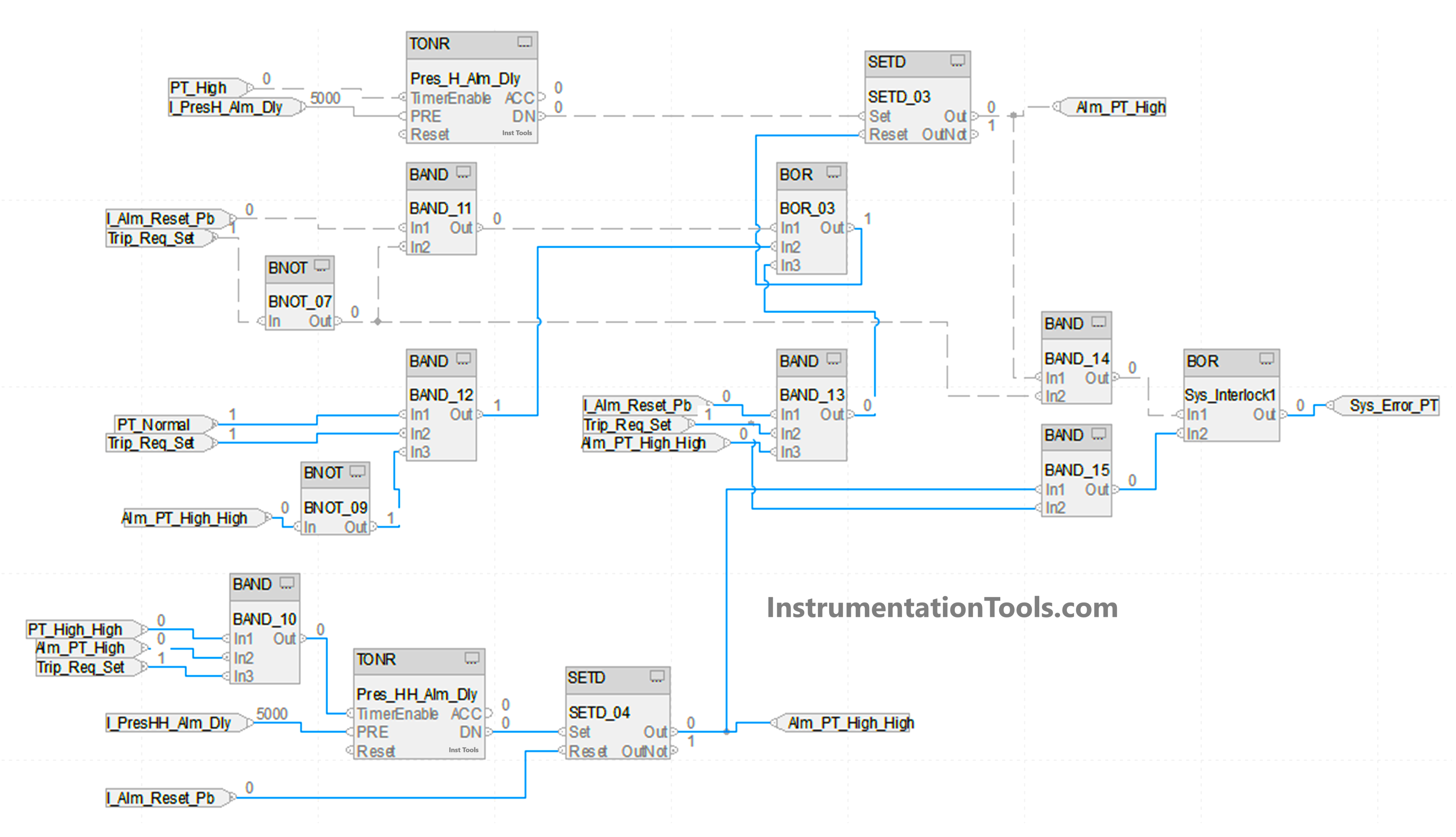
We will see the reset condition of the second case. The first alarm is reset by either this case – pressure transmitter normal and trip_req_set selected and negate alm_PT_high_high (means the alarm is gone if the pressure becomes normal before system trip) or by this case – alarm reset button and trip_req_set selected and alm_PT_high_high means the alarm is gone if the reset button is pressed after system trip).
The second alarm can be directly reset after pressing the reset button. The sys_error bit is set by using the AND logic of the second alarm generated and trip selection.
In this way, we saw how to write a PLC logic for analog alarms using a functional block diagram.
Read Next:
- Studio 5000 and FactoryTalk View Studio
- Analog Input Devices in Studio 5000
- Electrical Motor Forward Reverse PLC Logic
- Product Painting with Omron PLC Program
- Attendance System Program in Omron PLC




Your PLC logic for analog alarms seems well-structured, and I appreciate the clarity of the design. However, I noticed that certain details, like how the thresholds for alarms are set or how the system prioritizes multiple alarms, could use more explanation. It would also be helpful to include examples or diagrams to visualize the flow of logic for users unfamiliar with the system. Overall, it’s a good starting point, but a bit more detail would make it easier to follow and implement.