Inst ToolsInst ToolsInst Tools
  • Courses
  • Automation
    • PLC
    • Control System
    • Safety System
    • Communication
    • Fire & Gas System
  • Instrumentation
    • Design
    • Pressure
    • Temperature
    • Flow
    • Level
    • Vibration
    • Analyzer
    • Control Valve
    • Switch
    • Calibration
    • Erection & Commissioning
  • Interview
    • Instrumentation
    • Electrical
    • Electronics
    • Practical
  • Q&A
    • Instrumentation
    • Control System
    • Electrical
    • Electronics
    • Analog Electronics
    • Digital Electronics
    • Power Electronics
    • Microprocessor
  • Request
Search
  • Books
  • Software
  • Projects
  • Process
  • Tools
  • Basics
  • Formula
  • Power Plant
  • Root Cause Analysis
  • Electrical Basics
  • Animation
  • Standards
  • 4-20 mA Course
  • Siemens PLC Course
Reading: PLC Ladder Logic for Lube Oil Pump Motor
Share
Font ResizerAa
Inst ToolsInst Tools
Font ResizerAa
  • Courses
  • Design
  • PLC
  • Interview
  • Control System
Search
  • Courses
  • Automation
    • PLC
    • Control System
    • Safety System
    • Communication
    • Fire & Gas System
  • Instrumentation
    • Design
    • Pressure
    • Temperature
    • Flow
    • Level
    • Vibration
    • Analyzer
    • Control Valve
    • Switch
    • Calibration
    • Erection & Commissioning
  • Interview
    • Instrumentation
    • Electrical
    • Electronics
    • Practical
  • Q&A
    • Instrumentation
    • Control System
    • Electrical
    • Electronics
    • Analog Electronics
    • Digital Electronics
    • Power Electronics
    • Microprocessor
  • Request
Follow US
All rights reserved. Reproduction in whole or in part without written permission is prohibited.
Inst Tools > Blog > PLC Tutorials > PLC Ladder Logic for Lube Oil Pump Motor

PLC Ladder Logic for Lube Oil Pump Motor

Last updated: March 4, 2021 3:23 pm
Editorial Staff
PLC Tutorials
2 Comments
Share
2 Min Read
SHARE

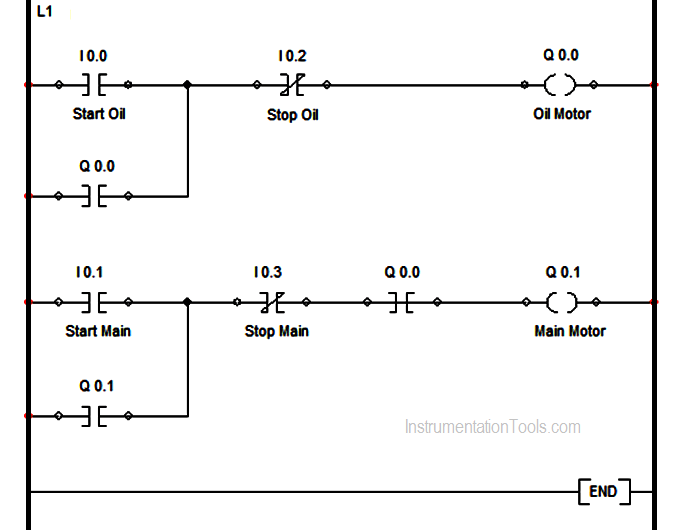
Design a ladder logic for providing lubricant for the gear box before the lathe spindle starts to run which aims to ensure that the lube oil pump motor starts first and the main motor starts subsequently ?

  • I0.0– START pushbutton to Start Oil Pump Motor
  • I0.1– START pushbutton to Stop Main Motor
  • I0.2– STOP pushbutton to Stop Oil Pump Motor
  • I0.3– STOP pushbutton to Stop Main Motor
  • Q0.0– Oil Pump Motor
  • Q0.1– Main Motor

This program is a typical application of the conditional control circuit. Q0.0 is ON when Oil Pump START button is pressed. Therefore, the oil pump will start to provide lubricant for the gear box of main motor (Q0.1).

Ladder Logic for Lube Oil Pump
PLC Ladder Logic for Lube Oil Pump Motor

Under the precondition of the operating state of the Oil pump, the main motor (Q0.1) will be ON when the Main motor START button is pressed. During the operation of main motor (Q0.1), oil pump (Q0.0) needs to provide lubricant continuously.

The oil pump will be stopped when Oil pump STOP button I0.2 is activated, and the main motor will be stopped when Main motor STOP button I0.3 is activated.

NOTE :

In real time applications, we may use Time Delays before starting main motor. After starting the Lube Oil Pump, there will be certain time delay ( say 30 sec, 2 min, 5 min) provided to make sure the lube oil pressure is sufficient before running main motor. In some cases time delays also provided during stopping the motors, based on specific applications.

If you liked this article, then please subscribe to our YouTube Channel for PLC and SCADA video tutorials.

You can also follow us on Facebook and Twitter to receive daily updates.

Read Next:

PLC Program Motor Starter

OFF Delay Timer using PLC

PLC, MCC, LCP & Pumps

SCADA Hardware and Software

Purpose of Marshalling Panel

Don't Miss Our Updates
Be the first to get exclusive content straight to your email.
We promise not to spam you. You can unsubscribe at any time.
Invalid email address
You've successfully subscribed !

Continue Reading

Machine Tool and Coolant Control: PLC Ladder Logic Design
Sequential Operation of Output Bits using Two Push buttons
Down Counter PLC Program
How to Detect Speed of Conveyor in PLC?
Automatic Highway Lights Program using RTC in Omron PLC
Motor Stop Interlock for Changing the Direction PLC Program
Share This Article
Facebook Whatsapp Whatsapp LinkedIn Copy Link
Share
2 Comments
  • Md.Salim says:
    November 9, 2019 at 9:09 pm

    Very nice…..

    Reply
    • Tafere says:
      March 17, 2022 at 11:27 am

      please give good notes about PLC ladder logic

      Reply

Leave a Reply Cancel reply

Your email address will not be published. Required fields are marked *

Stay Connected

128.3kFollowersLike
69.1kFollowersFollow
210kSubscribersSubscribe
38kFollowersFollow

Categories

Explore More

Types of Noise in Electronics
Unknown Do’s Need to Know as a PLC Programmer
Count the Number of Cartons in a Storage Area PLC Logic
Example of Automated Guided Vehicle with PLC
How to Download EcoStruxure Machine Expert? Schneider PLC Software
Design a Water Pump PLC Program using CX-Programmer
What is Trace Function in Tia Portal?
Basic Concepts of the Safety Relay

Keep Learning

Industrial Control Systems Security

Comparing ICS and IT Systems Security

HMI

Learn about SCADA and HMI Systems

How to use PLC With SQL Database

How to use PLC with SQL Database? – Basics & Tutorials

PLC Sequential Operation Example Program

PLC Sequential Operation Example Program

PLC ON DELAY TIMER FUNCTION

#6 PLC Best Practices – Validate Timers and Counters

How to Start Writing SCL in Siemens PLC

Rules for Writing SCL Language in Tia Portal

Omron PLC Online Training Course

Omron PLC Online Training Course

Intrinsic Safety Barriers

Intrinsically Safe Barriers Questions and Answers

Learn More

Bi-metal Temperature Gauge

Bi-metal Temperature Sensors

Transmitter Calibration Range of a Vessel Level

Transmitter Calibration Range of a Vessel Level

Analog Electronics Objective Questions

Analog Electronics Objective Questions – Set 4

Advantages and Applications of zigzag transformer

Safety PLC Programming steps

Safety Door Interlock PLC Program

Ion Spectrometers Questions & Answers

Instrumentation of Ion Spectroscopy

S7 1200 PLC Program

Siemens S7 1200 PLC configuration in TIA Portal

Remote Capillary Level Transmitter Mounted below the Zero Level

How to Calculate mmWC Range of Level Transmitter with Examples?

Menu

  • About
  • Privacy Policy
  • Copyright

Quick Links

  • Learn PLC
  • Helping Hand
  • Part Time Job

YouTube Subscribe

Follow US
All rights reserved. Reproduction in whole or in part without written permission is prohibited.
Welcome Back!

Sign in to your account

Username or Email Address
Password

Lost your password?