Step-by-step guide to plc ladder logic with set coil and reset coil example presented in this educational blog.
Please note: The logic diagram example is designed for educational use for students and engineering graduates to learn PLC fundamentals.
Set Coil and Reset Coil Example
Problem Statement
Design a PLC ladder logic for the following application.
We are using two toggle switches to control two motors.
If Switch 1 is ON, then Motor I and Motor II will be ON.
If Switch 1 is OFF, then Motor I and Motor II will be still ON.
If Switch 2 is ON, then Motor I and Motor II will be Off.
PLC Ladder Logic
Learn this PLC programming example with the below video.
IOs List
Digital Inputs:
The list of inputs given below.
Switch 1: I0.0
Switch 2: I0.1
Digital Outputs:
The list of outputs given below.
Motor 1: Q0.0
Motor 2: Q0.1
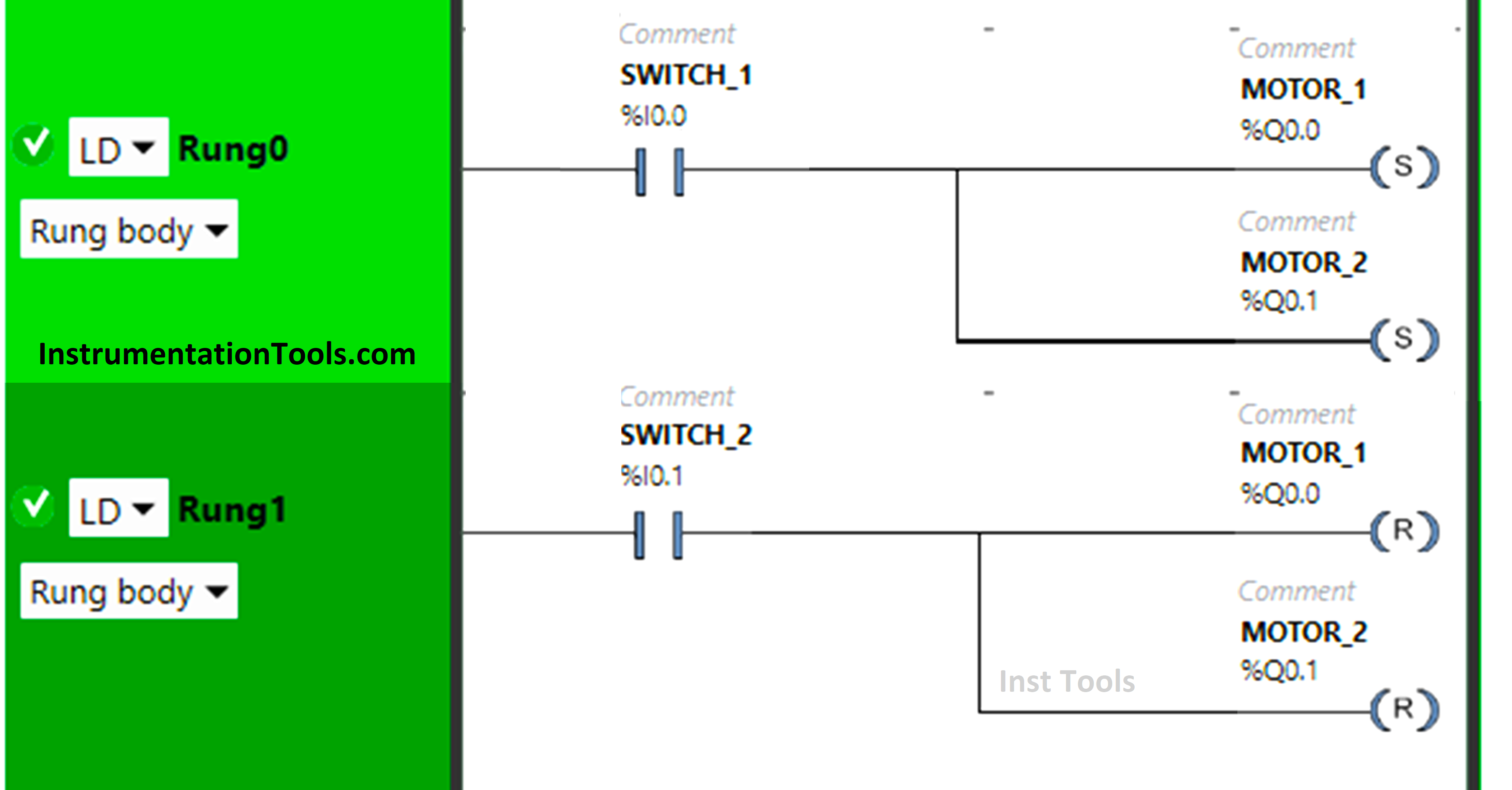
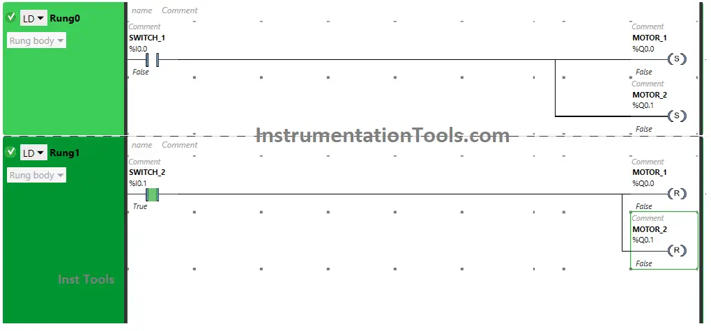
PLC Example using Set and Reset Coils
Program Description
- We used EcoStruxure Machine Expert software for PLC programming.
- In the above program, we have used Normally Open Contact for Switch 1 (I0.0) and Switch 2 (I0.1).
- Set and Reset Coils are used for both Motor 1 (Q0.0) and Motor 2 (Q0.1).
- For Motor 1 and Motor 2 to be ON, switch 1 should be ON.
- We have used set coils in Rung0 for the outputs, Motor 1 and Motor 2.
- Motor 1 and Motor 2 will remain ON when the input Switch 1 changes its state from true to false.
- In Rung 1, we have used Reset Coils for the outputs.
- When the Input Switch 2 gets ON, the reset coils will turn OFF the outputs.
Result
Let’s see the program result with different input simulations.
When Switch 1 is ON
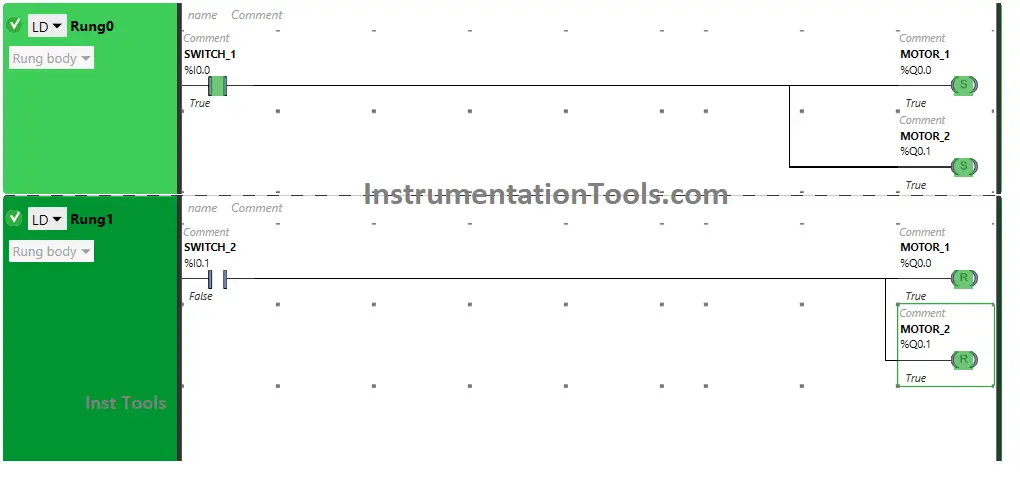
Switch 1, in the true state, will allow the signal to flow through it and Motor 1, and Motor 2 will get ON.
When Switch 1 is OFF
Motor 1 And Motor will remain ON when Switch 1 is turned OFF as Set Coils are used for these two Motors. The set coils will remain ON even when the input is changed to false.
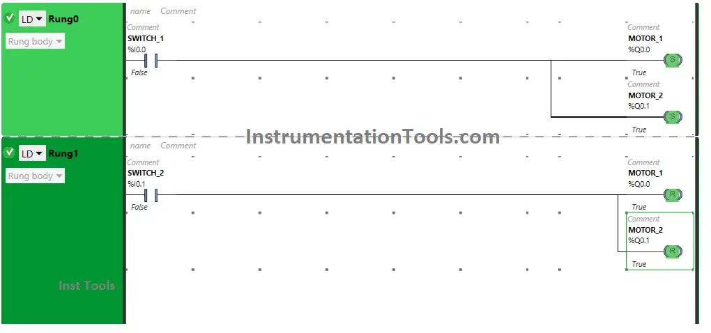
When Switch 2 is ON
When Switch 2 is turned ON, Motor 1 and Motor 2 will TURN OFF as Reset Coils are used for Motor 1 and Motor 2 in Rung1.
The reset coils, once activated, will turn OFF the outputs. And it will keep it OFF even when the input is turned OFF.
If you liked this article, please subscribe to our YouTube Channel for PLC and SCADA video tutorials.
You can also follow us on Facebook and Twitter to receive daily updates.
Read Next:
- Schneider PLC Programming Example
- PLC Ladder Diagram for Latching Concept
- PLC with 2 Toggle Switches and 4 Motors
- Rockwell CompactLogix and ControlLogix
- PLC Project Examples EcoStruxure Machine