Inst ToolsInst ToolsInst Tools
  • Ask
  • Courses
  • Videos
  • Q & A
    • Interview
      • Instrumentation
      • Electronics
      • Electrical
      • Practical Questions
    • MCQ
      • Instrumentation MCQ
      • Electrical MCQ
      • Electronics MCQ
      • Control Systems MCQ
      • Analog Electronics MCQ
      • Digital Electronics MCQ
      • Power Electronics MCQ
      • Microprocessor MCQ
      • Multiple Choice Questions
  • EE
    • Electronics
      • Electronics Q & A
      • Electronic Basics
      • Electronic Devices & Circuits
      • Electronics Animation
      • Digital Electronics
    • Electrical
      • Electrical Basics
      • Electrical Q & A
      • Power Electronics
      • Electrical Machines
      • Electrical Animation
      • Power Systems
      • Switchgear & Protection
      • Transmission & Distribution
  • Measure
    • Control Valves
    • Calibration
    • Temperature
    • Pressure
    • Flow
    • Level
    • Analyzers
    • Switches
    • Vibration
    • Solenoid Valve
  • Control
    • PLC Tutorials
    • Control Systems
    • Safety Instrumented System (SIS)
    • Communication
    • Fire & Gas System
  • More
    • Design
    • Tools
    • Animation
    • Basics
    • Formulas
    • Standards
    • TextBooks
    • Common
    • Software
    • Excel Tools
    • Erection & Commissioning
    • Process Fundamentals
    • Videos
    • Books
Search
All rights reserved. Reproduction in whole or in part without written permission is prohibited.
Reading: PLC Fault Diagnosis – PLC Training Documents
Share
Notification Show More
Font ResizerAa
Inst ToolsInst Tools
Font ResizerAa
  • Courses
  • PLC Tutorials
  • Control Systems
Search
  • Ask
  • Courses
  • Videos
  • Q & A
    • Interview
    • MCQ
  • EE
    • Electronics
    • Electrical
  • Measure
    • Control Valves
    • Calibration
    • Temperature
    • Pressure
    • Flow
    • Level
    • Analyzers
    • Switches
    • Vibration
    • Solenoid Valve
  • Control
    • PLC Tutorials
    • Control Systems
    • Safety Instrumented System (SIS)
    • Communication
    • Fire & Gas System
  • More
    • Design
    • Tools
    • Animation
    • Basics
    • Formulas
    • Standards
    • TextBooks
    • Common
    • Software
    • Excel Tools
    • Erection & Commissioning
    • Process Fundamentals
    • Videos
    • Books
Follow US
All rights reserved. Reproduction in whole or in part without written permission is prohibited.
Inst Tools > Blog > PLC Tutorials > PLC Fault Diagnosis – PLC Training Documents

PLC Fault Diagnosis – PLC Training Documents

In PLC fault diagnosis, it is necessary to understand what faults occur in the PLC modules and their respective LED indications.

Last updated: September 1, 2023 7:40 am
Viral Nagda
PLC Tutorials
No Comments
Share
5 Min Read
SHARE

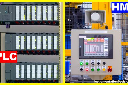
When you are working in a PLC system, it is necessary to understand what faults occur in the PLC modules. If a PLC programmer does not understand what fault is coming in the PLC and how to solve it, then he will take a very long time to troubleshoot the system.

Contents
PLC Fault DiagnosisLED Indications in PLC

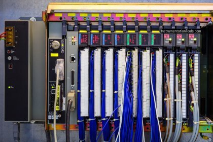
Every PLC and its modules have LEDs on them for visual easing and troubleshooting. Their detailed description is also given in their user manuals. So, it is important to understand how these LEDs function and once you get them, fault diagnosis becomes a very easy task for PLC programmers.

In this post, we will learn the concept of fault diagnosis in PLC.

PLC Fault Diagnosis

Let us have a look at some of the most general types of faults which can be identified with PLC LED’s:

Run LED is used to denote whether the module is functioning properly or not. If it is on continuously, then it means that the module is working properly. If this LED is off, then the module is faulty or off.

Err LED is used to denote whether the module is in error or not. If it is on continuously, then it is an internal module error. If it is flashing, then it means either the module is not configured properly or there is some issue in the PLC hardware connected to it. If it is off, then it means there is no fault in the module.

I/O LED is used to denote the exact status of the PLC IOs connected with the module. If it is on continuously, then it means there is some supply voltage error or short circuit. If it is off, then it means there is no error in the IO’s connected.

Channel LED is used to show the status of individual channels. If the LED is on continuously, then it means the channel is functioning properly. If it is flashing, then there is some error in it (broken wire or value out of range). If it is off, then it means the channel is not configured at all.

Some communication modules like Modbus RTU have a truth table of the LEDs, signifying each value of the same.

LED Indications in PLC

They are mostly as in the below table:

PLC Fault Diagnosis - PLC Training Documents

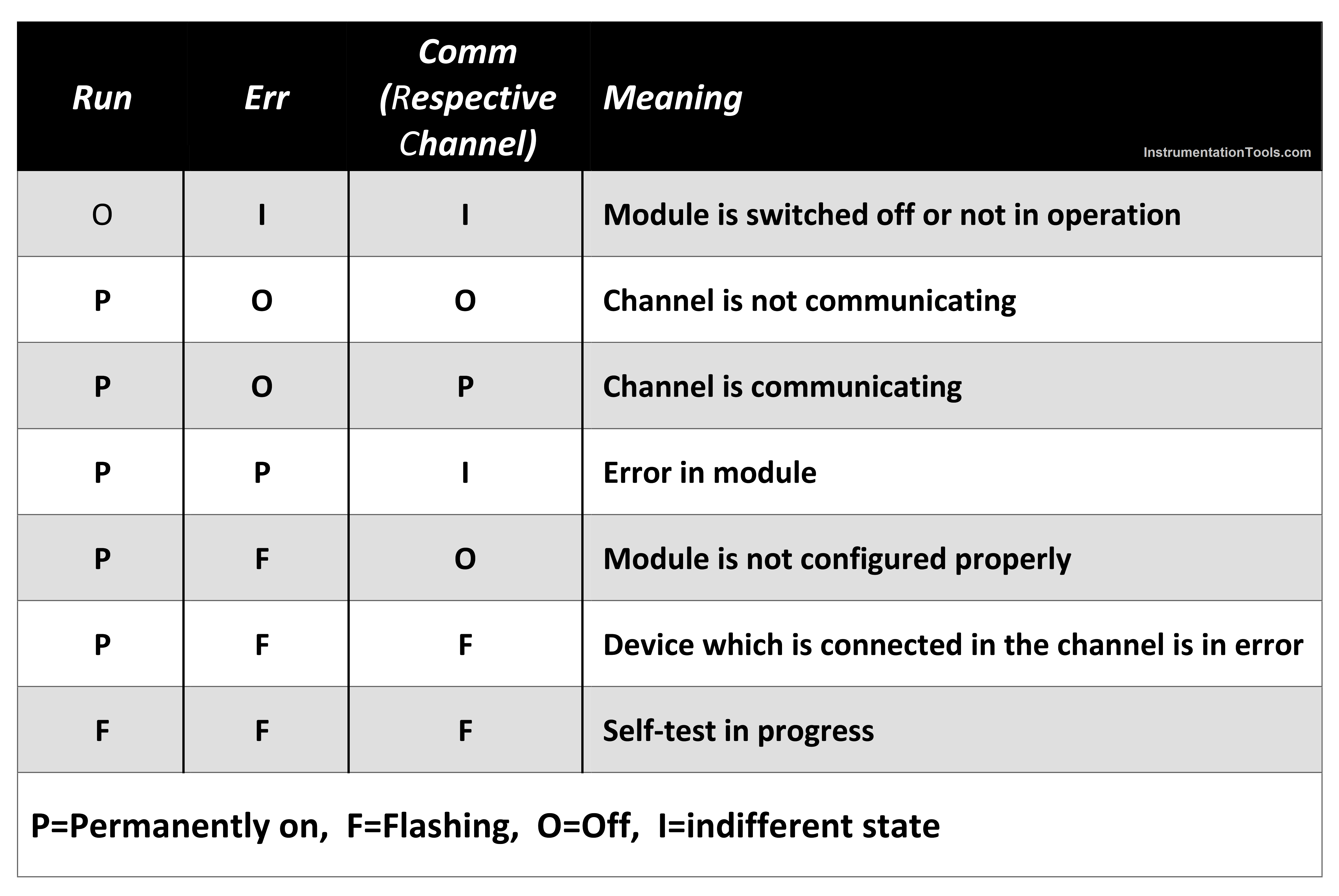
Note: The LED indications may vary based on the PLC model and brand. The above table is an example from one of the PLC models in the market.

Some communication modules like Modbus TCP/IP have slightly complicated LED diagnostics. But it is important to understand them for troubleshooting.

The module is running if the run LED is on and stopped if the LED is off. If Err LED is flashing, then it means the module is in error and if it is flashing, then it means either the module is not configured properly or there is some issue in the backplane if it is connected.

If the network status LED is off, then it means that the module is not communicating with any device; if it is on, then it is communicating with at least one device; if it flashing, then it means some duplicate IP address has been detected or some time out error.

In this way, we saw some general fault diagnoses in PLC.

If you liked this article, then please subscribe to our YouTube Channel for Instrumentation, Electrical, PLC, and SCADA video tutorials.

You can also follow us on Facebook and Twitter to receive daily updates.

Read Next:

  • PID Controllers in Control Systems
  • Update PLC Firmware Version
  • PLC ON-OFF Control with Hysteresis
  • Design Counters in PLC Program
  • Basic PID Controller Output Types
Don't Miss Our Updates
Be the first to get exclusive content straight to your email.
We promise not to spam you. You can unsubscribe at any time.
Invalid email address
You've successfully subscribed !
Typical HMI Screen Design for Water Treatment Plant
What is SCADA System?
#14 PLC Best Practices – Restrict Third-party Data Interfaces
Remote Factory Acceptance Test
How to Start Writing SCL Language in Siemens Tia Portal?
Share This Article
Facebook Whatsapp Whatsapp LinkedIn Copy Link
Share
Leave a Comment

Leave a Reply Cancel reply

Your email address will not be published. Required fields are marked *

Stay Connected

128.3kFollowersLike
69.1kFollowersFollow
208kSubscribersSubscribe
38kFollowersFollow

Categories

Recent Comments

  • Guifty Shimica on Top Non-PLC Certification Courses for Automation Professionals
  • Guifty Shimica on Top Non-PLC Certification Courses for Automation Professionals
  • MIHARITSOA Aina Sitraka on Top Non-PLC Certification Courses for Automation Professionals
  • Vaishnavi on Free Instrumentation Course for Trainee Engineers

Related Articles

On Delay Timer using PLC

ON Delay Timer using PLC

Car Parking System using PLC Programming

Car Parking System using PLC Programming

PLC Boxes Sorting Based on Height

PLC Programming: Sorting and Distribution of Boxes by Height

Omron PLC Instructions - Move, Move Bit, Move Digit

Move, Move Bit, Move Digit – Examples of Omron PLC Programs

PLC Logic to identify empty bottles in Packing

Automatic Empty Bottle detection using PLC Logic

What is meant by a SCADA System

Troubleshoot the Status of a PLC Via CPU Indicators

Free Schneider PLC Training - Automation Course

Free Schneider PLC Training – Automation Course

Automated Test Bench - Complex PLC Programming Examples

Automated Test Bench – Complex PLC Programming Examples

More Articles

Three Wire RTD Temperature Compensation

Ambient Temperature Effects on RTD

valve actuator yoke

Advantages and Disadvantages of Valve Actuators

IACS Network

Remote Connectivity to Industrial Automation Systems

Electrical Machines Questions and Answers

Synchronous Machines Power Factor Control Questions

What is a Compressor

What is a Compressor? Types of Compressors

Contact-Type-GWR-Level-Transmitter-Working-Animation

Probe Type GWR Level Transmitter Working Animation

PLC Temperature Control using Pulse Width Modulation

PLC Temperature Control using Pulse Width Modulation (PWM)

PLC Battery

Everything You Need to Know About PLC Battery

Follow US
All rights reserved. Reproduction in whole or in part without written permission is prohibited.
Welcome Back!

Sign in to your account

Username or Email Address
Password

Lost your password?