Inst ToolsInst ToolsInst Tools
  • Courses
  • Automation
    • PLC
    • Control System
    • Safety System
    • Communication
    • Fire & Gas System
  • Instrumentation
    • Design
    • Pressure
    • Temperature
    • Flow
    • Level
    • Vibration
    • Analyzer
    • Control Valve
    • Switch
    • Calibration
    • Erection & Commissioning
  • Interview
    • Instrumentation
    • Electrical
    • Electronics
    • Practical
  • Q&A
    • Instrumentation
    • Control System
    • Electrical
    • Electronics
    • Analog Electronics
    • Digital Electronics
    • Power Electronics
    • Microprocessor
  • Request
Search
  • Books
  • Software
  • Projects
  • Process
  • Tools
  • Basics
  • Formula
  • Power Plant
  • Root Cause Analysis
  • Electrical Basics
  • Animation
  • Standards
  • 4-20 mA Course
  • Siemens PLC Course
Reading: PLC Compressor Control Ladder Logic
Share
Notification Show More
Font ResizerAa
Inst ToolsInst Tools
Font ResizerAa
  • Courses
  • Design
  • PLC
  • Interview
  • Control System
Search
  • Courses
  • Automation
    • PLC
    • Control System
    • Safety System
    • Communication
    • Fire & Gas System
  • Instrumentation
    • Design
    • Pressure
    • Temperature
    • Flow
    • Level
    • Vibration
    • Analyzer
    • Control Valve
    • Switch
    • Calibration
    • Erection & Commissioning
  • Interview
    • Instrumentation
    • Electrical
    • Electronics
    • Practical
  • Q&A
    • Instrumentation
    • Control System
    • Electrical
    • Electronics
    • Analog Electronics
    • Digital Electronics
    • Power Electronics
    • Microprocessor
  • Request
Follow US
All rights reserved. Reproduction in whole or in part without written permission is prohibited.
Inst Tools > Blog > PLC Tutorials > PLC Compressor Control Ladder Logic

PLC Compressor Control Ladder Logic

Last updated: March 4, 2021 4:06 pm
Editorial Staff
PLC Tutorials
3 Comments
Share
4 Min Read
SHARE

The compressor can be run individually in manual or automatic mode.

Contents
PLC Compressor Control Ladder LogicProblem DiagramSolutionList of Inputs/OutputsLadder diagram for Compressors to run individually in manual or automatic modeProgram Description

PLC Compressor Control Ladder Logic

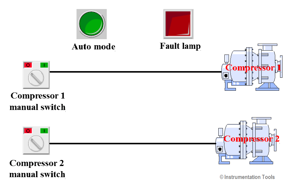
Two compressors are to be operated alternately from one AC power supply. If one compressor fails, the other one to be started automatically. The compressors can be run individually in manual or automatic mode. PLC executes the control and interlocking of both compressors.

Problem Diagram
PLC Compressor Control Ladder Logic

Solution

Selector switch is provided for each compressor to select the manual or automatic mode. Separate selectors switches provided for each compressor.

Here two operation modes are used for compressors. Manual mode and auto mode.

In manual mode operation by selector switch of each compressor. Compressor 1 can be started by selecting its selector switch and compressor 2 can be started by selecting its selector switch.

In auto mode operation, auto mode selector switch of each compressor should be selected. If one compressor is not working then second compressor will start automatically.

Here we considered enable command and start contactor for each compressor.

List of Inputs/Outputs

List of Inputs

  • I0.0 :- Selector switch auto/manual
  • I0.1 :- Selector switch, compressor 1 Manual
  • I0.2 :- Selector switch, compressor 2 Manual
  • I0.4 :- Pressure monitor
  • I0.5 :- Acknowledgment button, fault lamp
  • I0.6 :- Compressor 1 trip
  • I0.7 :- Compressor 2 trip

List of Outputs

  • Q0.0 :- Contactor, compressor 1
  • Q0.1 :- Start compressor 1
  • Q0.3 :- Contactor, compressor 2
  • Q0.4 :- Start compressor 2
  • Q0.5 :- Fault lamp

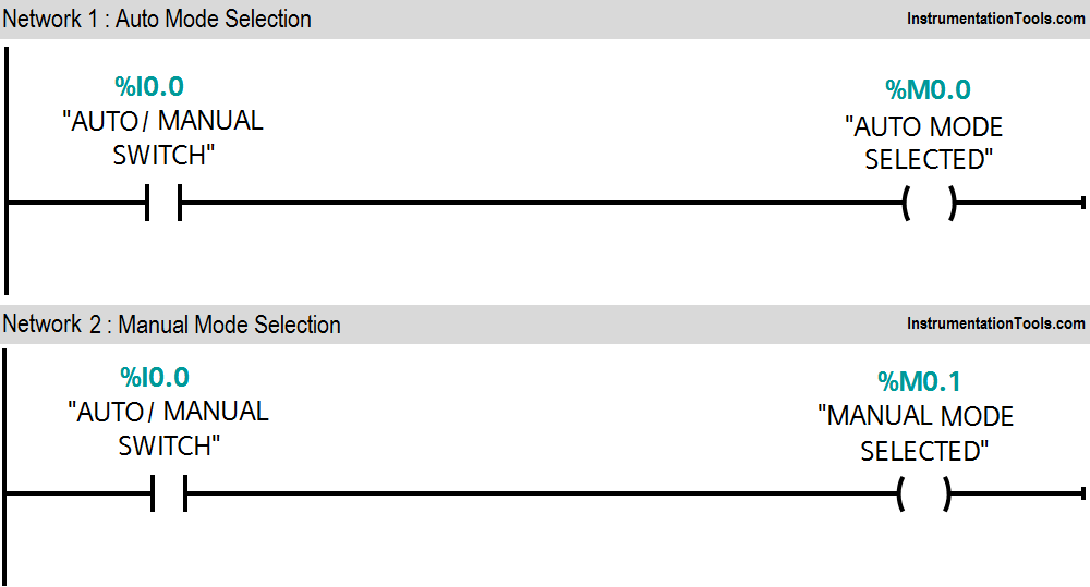
Ladder diagram for Compressors to run individually in manual or automatic mode
Air Compressor PLC Program
Compressor Ladder Logic
PLC Compressor Example
Compressor Control Ladder Logic
Compressor PLC Ladder Logic
PLC Air Compressor Logic

Program Description

In this program we have used Siemens S7-300 PLC and TIA Portal Software for programming.

Network 1 :-

If auto/manual switch is selected, auto mode selection (M0.0) is ON.

Network 2 :-

If auto/manual switch is not selected, manual mode selection (M0.1) is ON.

Network 3 :-

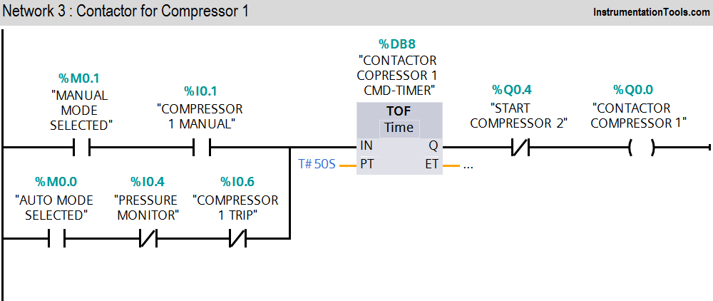
Compressor 1 contactor (Q0.0) can be started either selecting manual mode or auto mode.

Network 4 :-

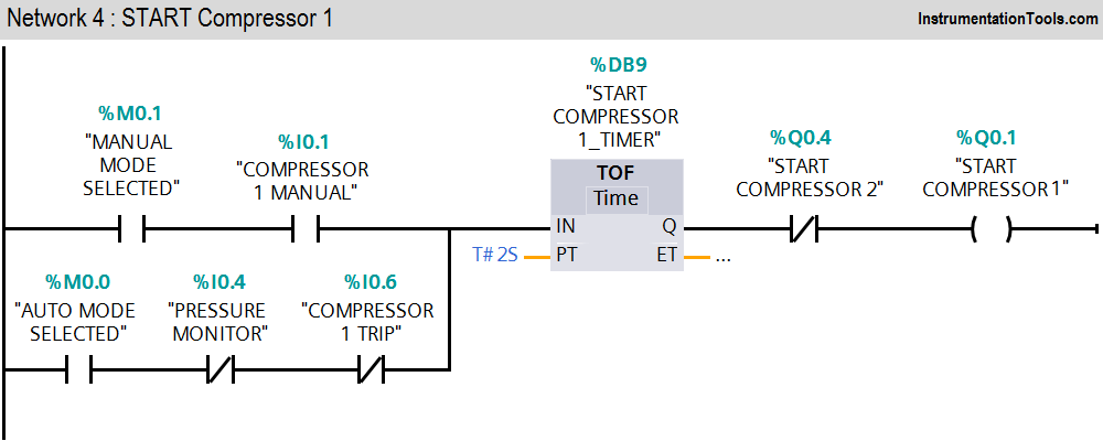
Compressor 1 enable command (Q0.1) will be ON in auto mode and manual mode.

Network 5 :-

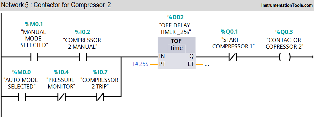
Compressor 2 contactor (Q0.3) can be started either selecting manual mode or auto mode.

Network 6 :-

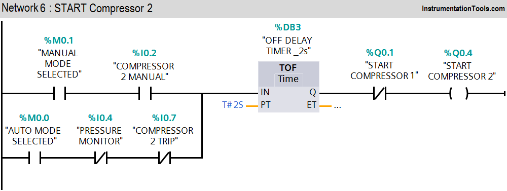
Compressor 2 enable command (Q0.4) will be ON in auto mode and manual mode.

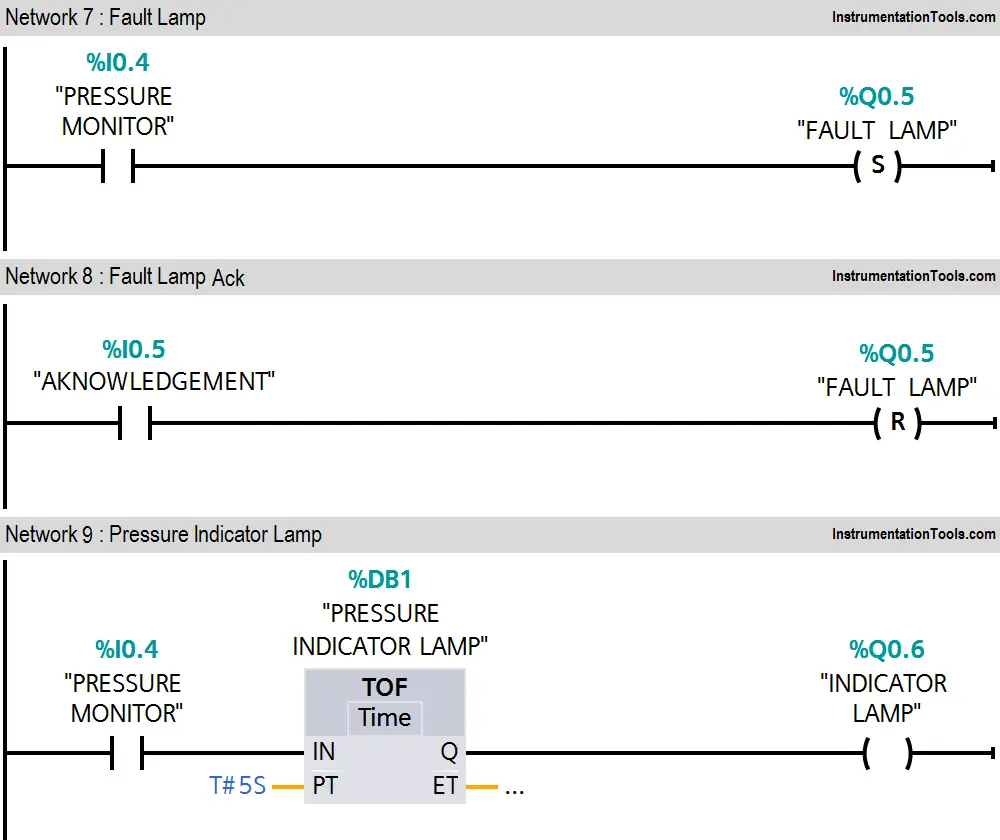
Network 7 :-

Fault indication lamp (Q0.5) will be ON if, pressure monitor input (I0.4) is activated.

Network 8 :-

Fault lamp (Q0.5) can be acknowledged by pressing acknowledged button (I0.5).

Network 9 :-

If pressure is not ok, pressure indicator lamp (Q0.6) will be ON and it will be OFF after 5s if in healthy condition.

Note :- Above application may be different from actual application. This example is only for explanation purpose only. We can implement this logic in other PLC also. This is the concept of different compressors control in auto mode and manual mode, we can use this concept in other examples also.

All parameters and graphical representations considered in this example are for explanation purpose only, parameters or representation may be different in actual applications. Also all interlocks are not considered in the application.

Author : Bhavesh

If you liked this article, then please subscribe to our YouTube Channel for PLC and SCADA video tutorials.

You can also follow us on Facebook and Twitter to receive daily updates.

Read Next:

PID Controller Functions

What is a Recorder ?

Process Dynamics & PID Tuning

Proof Testing of Safety Systems

PID Controller Bumpless Transfer
Don't Miss Our Updates
Be the first to get exclusive content straight to your email.
We promise not to spam you. You can unsubscribe at any time.
Invalid email address
You've successfully subscribed !

Continue Reading

PLC Program to Control Gas Pressure using Closed-Loop
Doll Claw Machine using Omron PLC Programming
CX-Programmer Products Sorting & Counting – Omron PLC
FC Function in Siemens PLC
Introduction to PLC – Advantages of PLC
Features of SCADA
Share This Article
Facebook Whatsapp Whatsapp LinkedIn Copy Link
Share
3 Comments
  • Faizal Raazy says:
    December 31, 2018 at 11:19 pm

    Great article

    Reply
  • adams says:
    January 1, 2019 at 2:16 pm

    Please do some examples in Rslogix 500 or 5000 thanks

    Reply
  • Tamilselvan says:
    June 28, 2025 at 1:13 pm

    Good sir

    Reply

Leave a Reply Cancel reply

Your email address will not be published. Required fields are marked *

Stay Connected

128.3kFollowersLike
69.1kFollowersFollow
210kSubscribersSubscribe
38kFollowersFollow

Categories

Explore More

PLC Fault Diagnosis – PLC Training Documents
What is Resources Tab in the Siemens PLC?
Design a Program Using Studio 5000 and FactoryTalk View Studio
User Defined Data Types (UDT) – Purpose, Need, Tutorial
Run 4 Motors Sequentially from Same Push button PLC Program
Upload Option Disabled in Siemens PLC
Augmented Reality and Virtual Reality in Industrial Automation
PLC Application for Stamping Operation – Example Programming

Keep Learning

PLC Program using START & STOP Buttons

PLC Program using START and STOP Buttons

Use of Comments in SCL Language

Use of Comments in SCL Language

Top Automation Vendors

Top Automation Vendors from Around the World – An Overview

Analog Measurement using Ladder Logic

Analog Measurement using Ladder Logic

Schneider PLC Programming Example

Schneider PLC Programming Example for Beginners

PLC Program Example on Multiple LEDs using Set Coil

PLC Program Example on Multiple LEDs using Set Coil

PLC engineering software

How to Download GX Works? Mitsubishi PLC Software

SCADA Standards

SCADA for Substation Automation

Learn More

Industrial safety Objective Questions and Answers

Top 10 Industrial safety Objective Questions

What is an Electromechanical Relay

Difference Between Solid State Relay and Electromechanical Relay

Difference Between Alternator and Generator

Difference Between Alternator and Generator?

DC machines and Induction Machines Viva Questions & Answers

Certified Control Systems Technician (CCST) Sample Questions

Certified Control Systems Technician (CCST) Questions

Weighing Scale Maintenance

Preventive Maintenance of Weighing Scale

Inspection of Control Valves

Inspection and Test Requirement of Control Valves

Advantages & Disadvantages of Air Insulated Substation

Advantages & Disadvantages of Air Insulated Substation

Menu

  • About
  • Privacy Policy
  • Copyright

Quick Links

  • Learn PLC
  • Helping Hand
  • Part Time Job

YouTube Subscribe

Follow US
All rights reserved. Reproduction in whole or in part without written permission is prohibited.
Welcome Back!

Sign in to your account

Username or Email Address
Password

Lost your password?