There are two different plants line in the garden. Both the plants types are different so we need to provide water as per demand of the plants. Design Automatic irrigation system for two different plants line using PLC ladder Logic.
Automatic Irrigation System

PLC Solution :
Here two types of methods are used for the plants.
For first plant line, we are using float switch because in this line it is necessary to maintain water level in the pool, so here water level will be controlled according to minimum level and maximum level.
In second plants line, we will operate different water pump as per moisture in the plants. If sensor detects low moisture, water pump will start and it will stop working when moisture is sufficient in the plants.
List of Inputs/Outputs
List of Inputs
- I1 :- Minimum level
- I2 :- Auto on
- I3 :- Moisture sensor
- I4 :- Maximum level
List of Outputs
- Q1 :- Water pump for plants line A
- Q2 :- Water pump for plants line B
Ladder Logic – Automatic irrigation system

PLC Logic Description
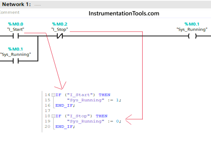
Network 1 :-
In this network we have used set reset logic for the water pump which is used for plants line A. When level is minimum in the pool, SET instruction will be executed and if level is normal, then reset condition will be executed.
Network 2 :-
Here water pump for the plants line A will be ON when both conditions (Set condition and auto on condition) are met.
Network 3 :-
When moisture is not available in the plants, water pump for the plants level B will be ON.
Note :- Above application may be different from actual application. This example is only for explanation purpose only. We can implement this logic in other PLC also. This is the simple automatic irrigation system for two different plants line using PLC; we can use this concept in other examples also.
All parameters and graphical representations considered in this example are for explanation purpose only, parameters or representation may be different in actual applications. Also all interlocks are not considered in the application.
If you liked this article, then please subscribe to our YouTube Channel for PLC and SCADA video tutorials.
You can also follow us on Facebook and Twitter to receive daily updates.
Read Next: