Inst ToolsInst ToolsInst Tools
  • Courses
  • Automation
    • PLC
    • Control System
    • Safety System
    • Communication
    • Fire & Gas System
  • Instrumentation
    • Design
    • Pressure
    • Temperature
    • Flow
    • Level
    • Vibration
    • Analyzer
    • Control Valve
    • Switch
    • Calibration
    • Erection & Commissioning
  • Interview
    • Instrumentation
    • Electrical
    • Electronics
    • Practical
  • Q&A
    • Instrumentation
    • Control System
    • Electrical
    • Electronics
    • Analog Electronics
    • Digital Electronics
    • Power Electronics
    • Microprocessor
  • Request
Search
  • Books
  • Software
  • Projects
  • Process
  • Tools
  • Basics
  • Formula
  • Power Plant
  • Root Cause Analysis
  • Electrical Basics
  • Animation
  • Standards
  • 4-20 mA Course
  • Siemens PLC Course
Reading: Basic PLC Alarm Programming Example
Share
Font ResizerAa
Inst ToolsInst Tools
Font ResizerAa
  • Courses
  • Design
  • PLC
  • Interview
  • Control System
Search
  • Courses
  • Automation
    • PLC
    • Control System
    • Safety System
    • Communication
    • Fire & Gas System
  • Instrumentation
    • Design
    • Pressure
    • Temperature
    • Flow
    • Level
    • Vibration
    • Analyzer
    • Control Valve
    • Switch
    • Calibration
    • Erection & Commissioning
  • Interview
    • Instrumentation
    • Electrical
    • Electronics
    • Practical
  • Q&A
    • Instrumentation
    • Control System
    • Electrical
    • Electronics
    • Analog Electronics
    • Digital Electronics
    • Power Electronics
    • Microprocessor
  • Request
Follow US
All rights reserved. Reproduction in whole or in part without written permission is prohibited.
Inst Tools > Blog > PLC Tutorials > Basic PLC Alarm Programming Example

Basic PLC Alarm Programming Example

This article explains the basic PLC alarm programming example with 8 switches combination logic to activate an output alarm.

Last updated: April 12, 2024 4:43 pm
Editorial Staff
PLC Tutorials
No Comments
Share
5 Min Read
SHARE

This article explains the basic PLC alarm programming example with 8 switches combination logic to activate an output alarm.

Contents
PLC Alarm ProgrammingAlarm VideoList of PLC InputsList of PLC OutputsLadder Diagram for AlarmProgram DescriptionPLC Program SimulationSwitch 2 is ON, or Switch 3 is ON, or both are ONSwitch 4 and Switch 5 are both ONOne or more of Switches 6,7 and 8 are ONSwitch 1 is ON and OFF

Important: The logic diagram example below is an educational resource for students and engineering graduates to understand PLC essentials.

PLC Alarm Programming

Problem Statement

Design a PLC ladder logic for the following application.

We are using 8 toggle switches to activate an Alarm.

An Alarm is ON when,

  • Switch 1 is OFF.
  • Switch 2 is ON, or Switch 3 is ON, or both are ON.
  • Switch 4 and Switch 5 are both ON.
  • One or more of Switches 6,7 and 8 are ON.

Alarm Video

Learn the PLC alarm example tutorial using the below video.

Step-by-Step Guide for Basic PLC Alarm Programming Example

List of PLC Inputs

The required digital inputs are listed below.

Switch 1: I0.0

Switch 2: I0.1

Switch 3: I0.2

Switch 4: I0.3

Switch 5: I0.4

Switch 6: I0.5

Switch 7: I0.6

Switch 8: I0.7

List of PLC Outputs

The required digital outputs are listed below.

Alarm: Q0.0

Ladder Diagram for Alarm
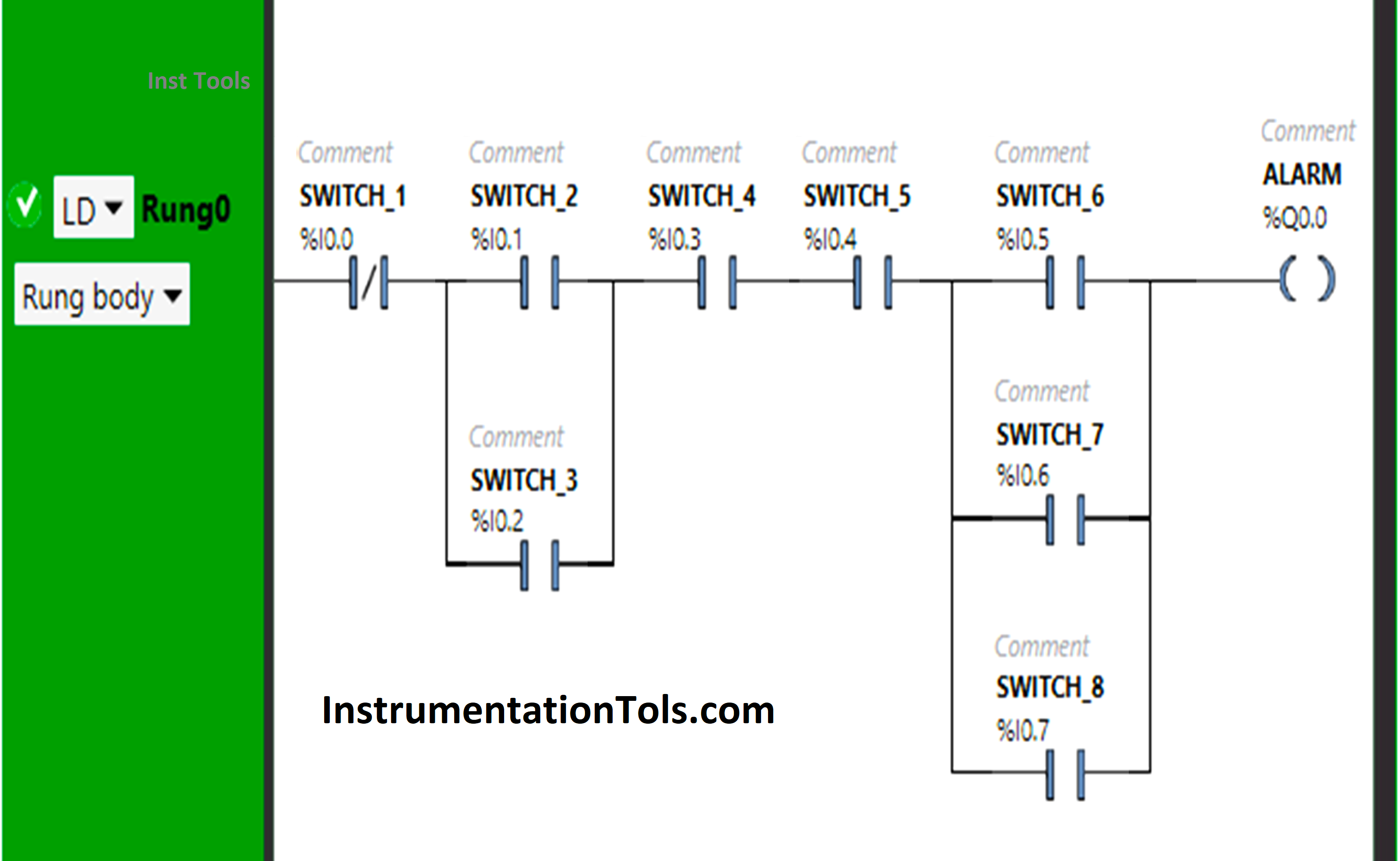
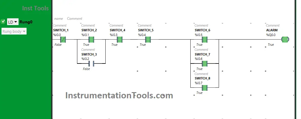
Basic PLC Alarm Programming Example
Fig: 1

Program Description

We used EcoStruxure Machine Expert Basic PLC software for programming.

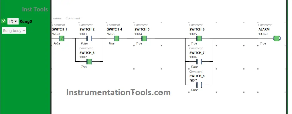
In the above program, we have used Normally Open Contacts as well as Normally Closed Contacts.

Normally Closed Contact is used for Switch 1 and when it is OFF, the Alarm will turn ON.

If Switch 1 is turned ON, the states of the remaining 7 Switches will not matter i.e., the Alarm will be OFF.

Switch 2 (I0.1) and Switch 3 (I0.2) are connected in parallel by implementing OR Logic Gate.

For the Alarm to be ON, one of the two switches i.e., Switch 2 or Switch 3 should be ON.

Switch 4 (I0.3) and Switch 5 (I0.4) are connected in a series that implements AND Logic Gate.

The alarm will TURN ON when both Switch 4 and Switch 5 are turned ON.

If one of the switches i.e., switch 6 or switch 7 or switch 8 is turned ON, the Alarm will TURN ON.

Switch 6 (I0.5), Switch 7 (I0.6), and Switch 8 (I0.7) implement OR Logic Gate as these are connected in parallel.

PLC Program Simulation

Here we simulate the program with different inputs. Note: The order of the input switch simulation may be in different sequences in the below results.

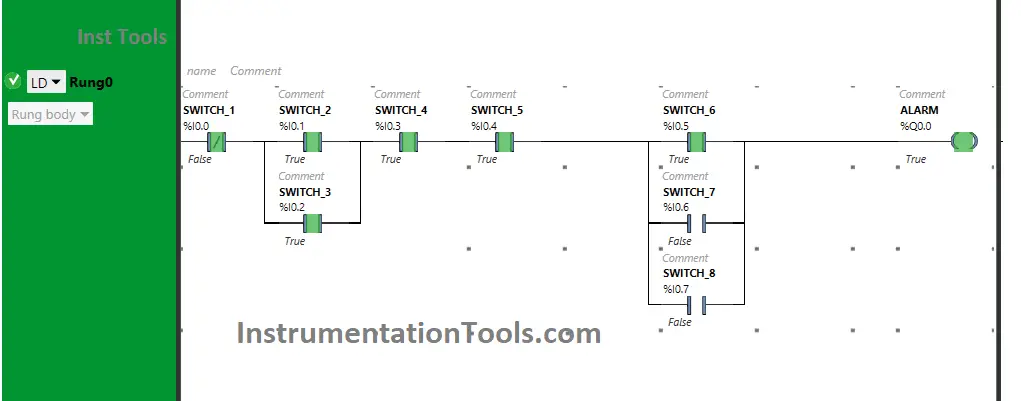
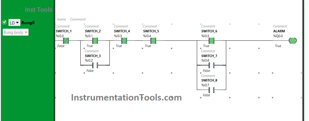
Switch 2 is ON, or Switch 3 is ON, or both are ON
Alarm System in PLC Logic
Fig: 2
Code of PLC Alarm Programming
Fig: 3
How to make PLC Alarm
Fig: 4

As Switch 2 and Switch 3 are connected in parallel implementing OR Logic Gate, so either Switch 2 or Switch 3 or both Switches, when turned ON will TURN ON the Alarm.

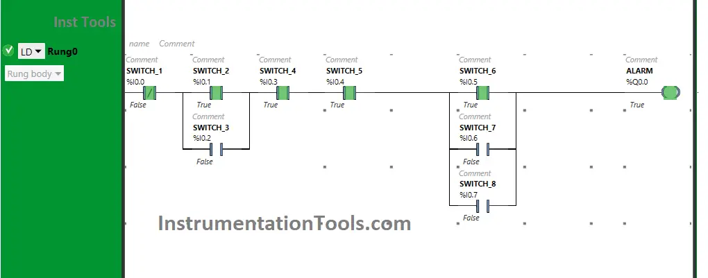
Switch 4 and Switch 5 are both ON
Alarm instruction in PLC Programming
Fig: 5

Turning ON both Switch 4 and Switch 5 will TURN ON the Alarm, as these are connected in series implementing AND Logic Gate.

If one of these switches i.e., switch 4 and Switch 5, when turned OFF, the Alarm will turn OFF.

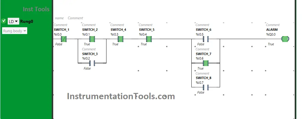
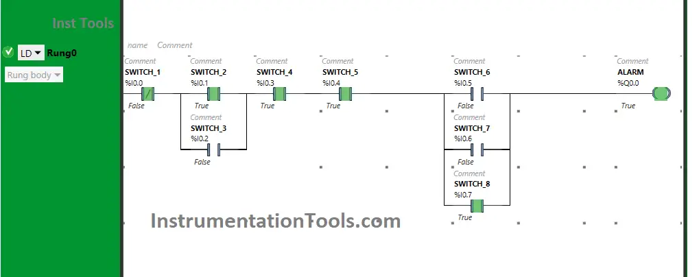
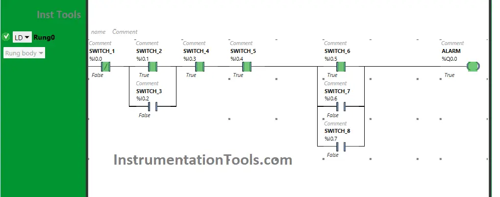
One or more of Switches 6,7 and 8 are ON
alarms within PLC cycle
Fig: 6
PLC Programming Tutorial Alarms
Fig: 7
alarm using PLC
Fig: 8
How to Write Ladder Logic for Alarm
Fig: 9

When One or more of Switches 6, 7, and 8 are turned ON, the Alarm will TURN ON as they are connected in parallel implementing OR Logic Gate.

The signal will flow through one of these switches and will reach the output. As a result, the alarm will be ON.

Switch 1 is ON and OFF

Alarm System in PLC Logic
Fig: 10

The alarm will TURN ON when Switch 1 is OFF as it is in the Normally Closed Contact State (with other switches in the ON state) but if Switch 1 is turned ON, it will not pass the signal to Output.

If you liked this article, please subscribe to our YouTube Channel for PLC and SCADA video tutorials.

You can also follow us on Facebook and Twitter to receive daily updates.

Read Next:

  • Log PLC Uptime and Trend it on HMI
  • Programmable Logic Controller Test
  • Validate PLC Inputs based on Plausibility
  • Connecting Allen Bradley PLC and PC
  • Advantages of Human-Machine Interface
Don't Miss Our Updates
Be the first to get exclusive content straight to your email.
We promise not to spam you. You can unsubscribe at any time.
Invalid email address
You've successfully subscribed !

Continue Reading

PLC Programming for Garden Sprinkler System
Automated Garage Gate Control – PLC Ladder Logic
Why Use Normally-Closed Contact for Stop Buttons?
Boolean Logic to PLC Programming
Basics of Sinking and Sourcing – Automation System MCQ
PLC Programming using Level Switches
Share This Article
Facebook Whatsapp Whatsapp LinkedIn Copy Link
Share
Leave a Comment

Leave a Reply Cancel reply

Your email address will not be published. Required fields are marked *

Stay Connected

128.3kFollowersLike
69.1kFollowersFollow
210kSubscribersSubscribe
38kFollowersFollow

Categories

Explore More

How to Connect PLC with SCADA System via OPC UA?
PLC 1 Push Button to Turn ON or OFF 1 Output
CRA Module in Schneider PLC – Remote IO Adapter Module
How to Convert Voltage to Current using Resistor ?
Basic Arithmetic Programming in Mitsubishi PLC
PLC Timer Example: Sequential Control of Three Lights with Reset
How to Take Program Backup from Physical PLC? – Siemens PLC
What is Recipe Management in SCADA?

Keep Learning

Communication Protocols in PLC

Various Communication Protocols in PLC

T-Junction Traffic Control System

T-Junction Traffic Control System – PLC Programming

TIA Portal MOVE Instruction

MOVE Instruction in PLC – What You Need to Know?

Introduction to GOC controllers

Mitsubishi Electric GOC Controllers

Extended Timer Logic in PLC

Extended Timer Logic in PLC

Relay Internal Parts

Relay Operation, Types, Symbols & Characteristics

Traffic Barrier Control

PLC Programming for Traffic Barrier Control

Siemens Profibus Interface DP

How to Create New Project Using Simatic Manager

Learn More

Chlorine Cylinders

Chlorine Gas Hazards

Introduction to SCL Programming in Siemens PLC

Types of Expressions in the SCL Language of the Tia Portal

Sequential Operation of Output Bits using Two Push buttons

Sequential Operation of Output Bits using Two Push buttons

Capacitance Pressure Sensor Principle

Electronic Pressure Sensors Principle

Network topologies

Different Types of Network Topologies

Flow Measurement Multiple Choice Questions

Flow Measurement Multiple Choice Questions

Automation in Mining Industry

Industrial Automation in the Mining Industry

How to do Force in GE PLC Proficy Machine Edition?

Menu

  • About
  • Privacy Policy
  • Copyright

Quick Links

  • Learn PLC
  • Helping Hand
  • Part Time Job

YouTube Subscribe

Follow US
All rights reserved. Reproduction in whole or in part without written permission is prohibited.
Welcome Back!

Sign in to your account

Username or Email Address
Password

Lost your password?