In a half-controlled rectifier with an RL load and a freewheeling diode, the circuit configuration typically consists of a single-phase diode rectifier with an inductive load and an additional diode (freewheeling diode) connected in parallel with the load.
The freewheeling diode allows the inductive load to discharge its energy when the main thyristor(s) are turned off. This configuration is often used in applications where controlled rectification is needed, and the load has significant inductance.
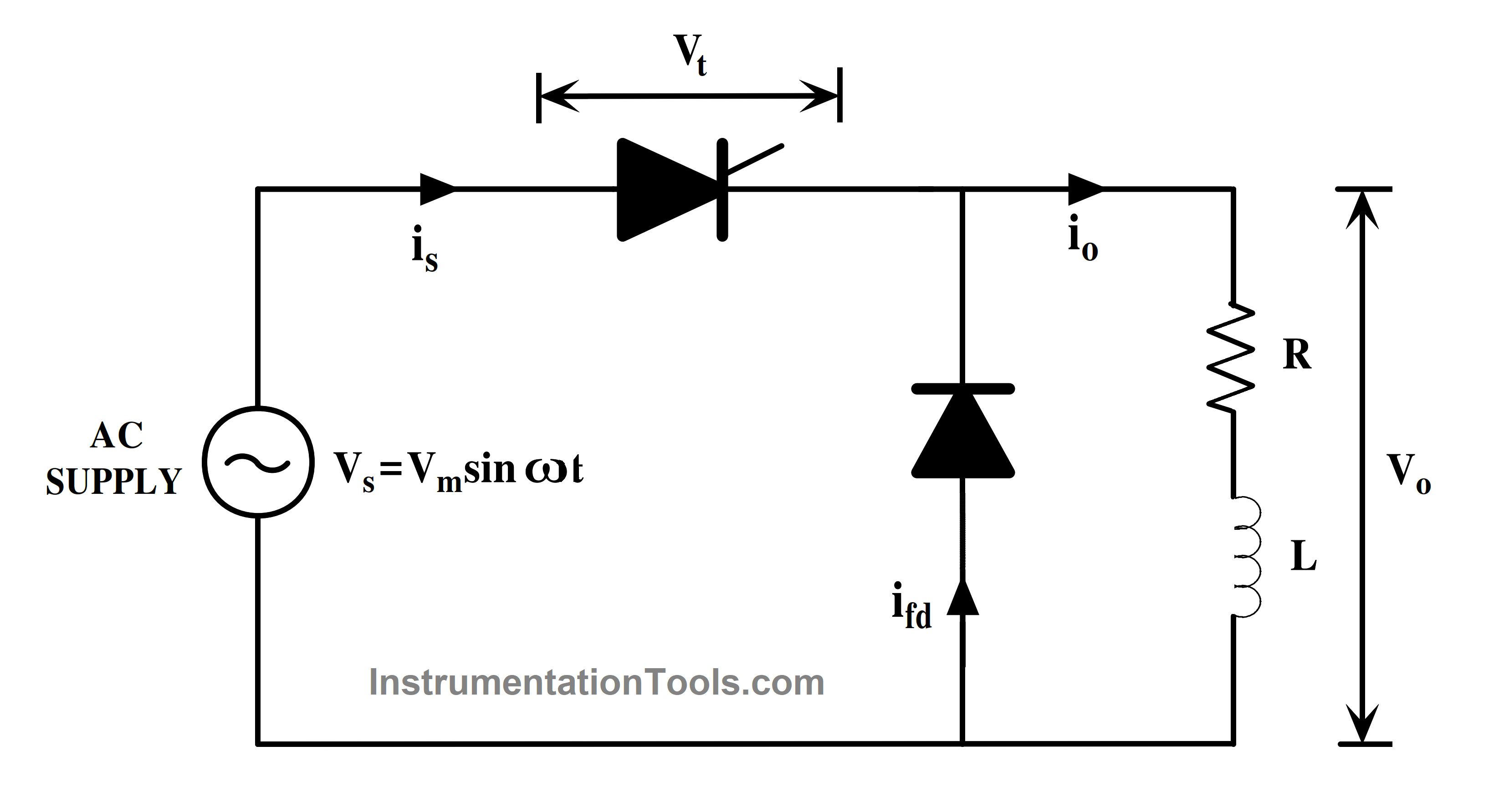
Fig. 1. Single Phase Half-controlled Rectifier RL Load With FD
Thyristor(s) (SCR): Thyristors are semiconductor devices that act as controlled rectifiers.
Diode (Freewheeling Diode): A diode connected in parallel with the load to provide a path for the inductive load current when the thyristor is off.
Inductive Load (RL): A load with inductance, such as a motor or a transformer.
Resistor (R): A resistor may be connected in series with the inductive load to limit the current.
a. Positive Half-Cycle:
During the positive half-cycle of the input AC voltage, the thyristor is triggered at α (firing angle) into conduction. The thyristor conducts, allowing the current to flow through the inductive load (RL) and the thyristor. The load current rises, and energy is stored in the inductor.
At the end of the positive half-cycle, the input voltage reverses polarity, causing the thyristor to naturally turn off (it is a half-controlled rectifier, so the thyristor only conducts during positive half-cycles).
When the thyristor turns off, the inductive load tries to maintain the current flow. However, since the thyristor is off, the freewheeling diode (FD) provides a path for the inductive current to circulate. The diode conducts, allowing the energy stored in the inductor to be released and the current to continue flowing through the load.
b. Negative Half-Cycle:
During the negative half-cycle of the input AC voltage, both the thyristor and the freewheeling diode FD are reverse-biased and, therefore, do not conduct. No current flows through the load during this half-cycle.
This configuration allows for controlled rectification during the positive half-cycles while providing a path for the inductive load current to circulate during the off periods (negative half-cycles) through the freewheeling diode. The resistor (R) can be added in series with the load to limit the current and control the circuit behavior further.
The circuit turn of time tc = π/ω
The SCR Conducts from α to 2π+ α to 3π and so on and FD is reverse biased during this condition.
The circuit’s voltage equation is stated as
θ = tan-1 (XL/R) and XL = ωl. Here, θ is the angle by which rms current Is lags Vs.
Fig. 2. Half Controlled Rectifier Output RL Load With FD
Transient component it can be obtained by simplifying the following equation
During the negative cycle, the load current continuously conducts with the help freewheeling diode from π to 2π + α, 3π to 4π+ α and so on.
The load current equation during the Freewheeling diode period is given as
The average load voltage Vo for the single-phase half-controlled rectifier is given by
The Load current IO is contributed by SCR from α to π, (2π + α) to 3π and so on, and by FD from 0 to α, it to (2π + α) and so forth. For ωt = α to π, (2π + α) to 3n, and so on, the waveshape of the thyristor current is the same as the waveshape of the io. Similar to this, for ωt = 0° to α, π to (2π + α), and so on, the waveform of the FD current, ifd, is the same as the waveform of the io.
While energy stored in the inductance L is returned to the source as power p2 for π to β (v0 is negative and i0 is positive), the load consumes power p1 from the source for α to π (both v0 and i0 are positive). Therefore, the difference between these two powers, p1 and p2, is the amount of net power used by the load.
For α to π, the load consumes energy, whereas for π to (2π + α), energy stored in L is transferred to the load resistance R via the FD. As a result, more electricity is used by the load. Therefore, it can be argued that using FD results in greater power being delivered to the load for the same firing angle.
With FD, the load current waveform is enhanced. Thus, utilizing a freewheeling diode has the following benefits:
The freewheeling diode prevents the load voltage v0 from going negative. FD kicks in whenever load voltage tends to drop. As a result, the load current is switched from the main thyristor to the FD, restoring the thyristor’s capacity for forward blocking.
As can be observed from the fig, the supply current is obtained from the source unidirectionally and as DC pulses. Thus, a single-phase half-wave converter adds a DC component to the supply line. This is bad since it causes the supply transformer to get saturated and other issues (harmonics, etc.).
% Parameters

R = 10;                  % Load resistance (in ohms)

L = 0.1;                  % Load inductance (in Henrys)

Vrms = 230;          % RMS input voltage (in volts)

Frequency = 50;    % Frequency of the input AC voltage (in Hz)

Rf = 0.01;              % Freewheeling diode forward resistance (in ohms)

Vf = 0.7;                % Freewheeling diode forward voltage (in volts)

% Convert RMS voltage to peak voltage

Vpeak = Vrms * sqrt(2);

% Time vector

t = 0:1e-6:0.02;     % Time from 0 to 20 milliseconds with a step of 1 microsecond

% Input voltage (sinusoidal)

Vin = Vpeak * sin(2 * pi * Frequency * t);

% Half-controlled rectifier operation

alpha = 45;

% Conduction angle (in degrees)

alpha_rad = deg2rad(alpha);

Vout = zeros(size(t));

% Rectifier operation based on conduction angle

for i = 1:length(t)

if Vin(i) * sin(alpha_rad) > 0

Vout(i) = Vin(i) * sin(alpha_rad);

else

Vout(i) = 0;

end

end

% Freewheeling diode operation

for i = 1:length(t)

if Vin(i) * sin(alpha_rad) <= 0

Vout(i) = Vf;

end

end

% Calculate current through RL load

I = Vout / (R + Rf) * exp(-Rf / L * t) .* (1 - exp(-L / (R + Rf) * t));

% Plot input voltage, output voltage, and load current

figure;

subplot(3,1,1);

plot(t, Vin, 'r');

title('Input Voltage');

xlabel('Time (s)');

ylabel('Voltage (V)');

subplot(3,1,2);

plot(t, Vout, 'b');

title('Output Voltage');

xlabel('Time (s)');

ylabel('Voltage (V)');

subplot(3,1,3);

plot(t, I, 'g');

title('Load Current');

xlabel('Time (s)');

ylabel('Current (A)');Fig.3. Simulink Circuit of Half-controlled Rectifier RL Load With FD
Fig.4 Simulink Response of Half-controlled Rectifier RL Load With FD
If you liked this article, then please subscribe to our YouTube Channel for Instrumentation, Electrical, PLC, and SCADA video tutorials.
You can also follow us on Facebook and Twitter to receive daily updates.
Read Next:
In this post, we will learn the basic requirements for a network switch to be…
The PLC panel and MCC panel interface signals are start, stop, run feedback, trip, local…
In this article, we are going to discuss about shutter door control using induction motor…
Electrical Drives control the motion of electric motors. Motion control is required in industrial and…
PLC ladder logic design to control 3 motors with toggle switch and explain the program…
VFD simulator download: Master the online tool from the Yaskawa V1000 & programming software for…


