Inst ToolsInst ToolsInst Tools
  • Courses
  • Automation
    • PLC
    • Control System
    • Safety System
    • Communication
    • Fire & Gas System
  • Instrumentation
    • Design
    • Pressure
    • Temperature
    • Flow
    • Level
    • Vibration
    • Analyzer
    • Control Valve
    • Switch
    • Calibration
    • Erection & Commissioning
  • Interview
    • Instrumentation
    • Electrical
    • Electronics
    • Practical
  • Q&A
    • Instrumentation
    • Control System
    • Electrical
    • Electronics
    • Analog Electronics
    • Digital Electronics
    • Power Electronics
    • Microprocessor
  • Request
Search
  • Books
  • Software
  • Projects
  • Process
  • Tools
  • Basics
  • Formula
  • Power Plant
  • Root Cause Analysis
  • Electrical Basics
  • Animation
  • Standards
  • 4-20 mA Course
  • Siemens PLC Course
Reading: pH Transmitter Problem
Share
Font ResizerAa
Inst ToolsInst Tools
Font ResizerAa
  • Courses
  • Design
  • PLC
  • Interview
  • Control System
Search
  • Courses
  • Automation
    • PLC
    • Control System
    • Safety System
    • Communication
    • Fire & Gas System
  • Instrumentation
    • Design
    • Pressure
    • Temperature
    • Flow
    • Level
    • Vibration
    • Analyzer
    • Control Valve
    • Switch
    • Calibration
    • Erection & Commissioning
  • Interview
    • Instrumentation
    • Electrical
    • Electronics
    • Practical
  • Q&A
    • Instrumentation
    • Control System
    • Electrical
    • Electronics
    • Analog Electronics
    • Digital Electronics
    • Power Electronics
    • Microprocessor
  • Request
Follow US
All rights reserved. Reproduction in whole or in part without written permission is prohibited.
Inst Tools > Blog > Analyzers > pH Transmitter Problem

pH Transmitter Problem

Last updated: October 4, 2020 6:50 pm
Editorial Staff
Analyzers Practical Questions
2 Comments
Share
3 Min Read
SHARE

A newly-installed pH transmitter does not seem to be measuring the pH of the process liquid accurately. The indicating controller’s display does not match the display of the hand-held pH meter used by an operator.
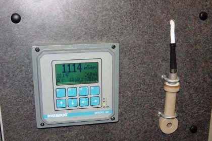
Contents
pH TransmitterSolution:

pH Transmitter

4-wire pH Transmitter Problem

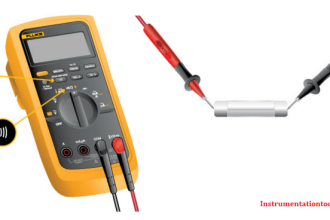
The calibrated range of the 4-wire pH transmitter is supposed to be 2 to 12 pH, with a 4 to 20 mA signal output range. An instrument technician begins to diagnose the problem by taking a loop calibrator and measuring the current signal being sent to the indicating controller. The loop calibrator registers 15.43 milliamps.

Based on this information, determine where the problem is in this system. Also, show how the loop calibrator could be connected to the wiring to measure the loop current (specifying the proper calibrator mode as well).

Solution:

15.43 milliamps of current equates to a percentage value of 71.44%

(15.43 − 4) / 16 × 100% = 71.44%

This, in turn, represents a pH value of:

0.7144 × (12 − 2) + 2 = 9.144 pH

This largely agrees with the controller’s display, which tells us there is a slight calibration error on either the part of the controller or the resistor. The huge discrepancy between this calculated pH value and what the hand-held pH meter registers, however, tells us there is either a problem with the pH transmitter, the pH probe, or the hand-held meter. We may further conclude there is no problem with the 250 resistor or the indicating controller.

The proper setup of the loop calibrator is to place it into the “READ” (measure) mode so that it functions as a simple ammeter, then connect it in series with the output of the 4-wire transmitter. This may be done either with the indicating controller still in the circuit, or removed from the circuit.

If the technician had no test equipment except for a voltmeter, could a good diagnostic test still be made in this system?

Share Your Answer through comments.

Read Next:

  • Basics of pH measurement
  • Transmitter Accuracy
  • Calculate Transmitter Output
  • Instrumentation Quiz
  • Calculate Process Variable

Credits: Tony R. Kuphaldt

Don't Miss Our Updates
Be the first to get exclusive content straight to your email.
We promise not to spam you. You can unsubscribe at any time.
Invalid email address
You've successfully subscribed !

Continue Reading

Draw a ladder logic circuit for the electric motor of an air compressor ?
Chromatograph Sample Valves
Problem on Solar Hot Air Collector and Variable Speed Fan
Solenoid Valves Practical Problems
Practical Process Control System Questions & Answers – 10
Sketch a Ladder Diagram for PLC to Energize the Lamp
Share This Article
Facebook Whatsapp Whatsapp LinkedIn Copy Link
Share
2 Comments
  • Ramjan Safoor says:
    January 13, 2020 at 11:34 am

    Dear All,

    The first thing I would do is check the Lab meter with two pH buffer solutions – say 7 & 12 pH.

    Clean the process pH probe and check it with the same buffer and note the differences.

    The third is to check if the controller output range is set accordingly to the valves PH 2 = 4 mA and pH 12 = 20mA.

    If it’s good then we can recalibrate the pH probe accordingly.

    Rgds SR

    Reply
  • galih says:
    January 14, 2020 at 2:41 pm

    Dear All,

    I would check a sample to the laboratory then compare the pH value with Portable pH Meter & Transmitter.

    After that calibrate pH sensor (Portable pH Meter & Transmitter) with the same buffer, if necessary.

    Galih

    Reply

Leave a Reply Cancel reply

Your email address will not be published. Required fields are marked *

Stay Connected

128.3kFollowersLike
69.1kFollowersFollow
210kSubscribersSubscribe
38kFollowersFollow

Categories

Explore More

Determine the Pressure at Each Port of DP Transmitter
DP Transmitter Located 10 feet Beneath the Vessel
Sling Psychrometer Principle
PLC Practice Questions
Stripper Overhead Temperature Control System
Moisture Calculator
Sodium Analyzer Problems and Troubleshooting Steps
TOC Analyzer Working Principle

Keep Learning

Calculate Total Hydrostatic Pressure at Bottom of Vessel

Calculate Total Hydrostatic Pressure at Bottom of Vessel

pH Analyzer Calibration and Troubleshooting

Troubleshooting pH Analyzer Common Problems

Humidity Sensing Absorption Hydrometer Principle

Humidity Sensing Absorption Hydrometer Principle

pressure switch control two lamps wiring

Draw Wiring of a Pressure Switch to control two lamps

Calculate Temperature of Four Wire RTD

Calculate the Temperature of 4 Wire RTD

mass spectrometer sample system

Mass Spectrometer Working Principle

reactor vessel

Practical Process Control System Questions & Answers – 5

Electrical Conductivity Meter

What is the Application of Electrical Conductivity Meter?

Learn More

Level Gauges

Level Gauge Design

Programmable Logic Controller (PLC) Questions and Answers

Programmable Logic Controller (PLC) Questions and Answers – 3

RTD Questions & Answers

RTD Questions and Answers

Root Cause Analysis of Differential Pressure Level Transmitter

Root Cause Analysis of Differential Pressure Level Transmitter

Closed-Tank-DP-Type-Level-Measurement-with-Dry-leg-and-transmitter-installed-below-tapping-point

Level Measurement with Dry leg and Installed Below Tapping Point

Ultrasonic level measurement

Ultrasonic Level Measurement

Questions and Answers on Motors and Generators

HT Motor Problem appears after Disassembly and Reassembly

Instrument Air Compressor Control Philosophy

Instrument Air Compressor Control Philosophy

Menu

  • About
  • Privacy Policy
  • Copyright

Quick Links

  • Learn PLC
  • Helping Hand
  • Part Time Job

YouTube Subscribe

Follow US
All rights reserved. Reproduction in whole or in part without written permission is prohibited.
Welcome Back!

Sign in to your account

Username or Email Address
Password

Lost your password?