Inst ToolsInst ToolsInst Tools
  • Ask
  • Courses
  • Videos
  • Q & A
    • Interview
      • Instrumentation
      • Electronics
      • Electrical
      • Practical Questions
    • MCQ
      • Instrumentation MCQ
      • Electrical MCQ
      • Electronics MCQ
      • Control Systems MCQ
      • Analog Electronics MCQ
      • Digital Electronics MCQ
      • Power Electronics MCQ
      • Microprocessor MCQ
      • Multiple Choice Questions
  • EE
    • Electronics
      • Electronics Q & A
      • Electronic Basics
      • Electronic Devices & Circuits
      • Electronics Animation
      • Digital Electronics
    • Electrical
      • Electrical Basics
      • Electrical Q & A
      • Power Electronics
      • Electrical Machines
      • Electrical Animation
      • Power Systems
      • Switchgear & Protection
      • Transmission & Distribution
  • Measure
    • Control Valves
    • Calibration
    • Temperature
    • Pressure
    • Flow
    • Level
    • Analyzers
    • Switches
    • Vibration
    • Solenoid Valve
  • Control
    • PLC Tutorials
    • Control Systems
    • Safety Instrumented System (SIS)
    • Communication
    • Fire & Gas System
  • More
    • Design
    • Tools
    • Animation
    • Basics
    • Formulas
    • Standards
    • TextBooks
    • Common
    • Software
    • Excel Tools
    • Erection & Commissioning
    • Process Fundamentals
    • Videos
    • Books
Search
All rights reserved. Reproduction in whole or in part without written permission is prohibited.
Reading: Orifice Plate Turndown ratio
Share
Notification Show More
Font ResizerAa
Inst ToolsInst Tools
Font ResizerAa
  • Courses
  • PLC Tutorials
  • Control Systems
Search
  • Ask
  • Courses
  • Videos
  • Q & A
    • Interview
    • MCQ
  • EE
    • Electronics
    • Electrical
  • Measure
    • Control Valves
    • Calibration
    • Temperature
    • Pressure
    • Flow
    • Level
    • Analyzers
    • Switches
    • Vibration
    • Solenoid Valve
  • Control
    • PLC Tutorials
    • Control Systems
    • Safety Instrumented System (SIS)
    • Communication
    • Fire & Gas System
  • More
    • Design
    • Tools
    • Animation
    • Basics
    • Formulas
    • Standards
    • TextBooks
    • Common
    • Software
    • Excel Tools
    • Erection & Commissioning
    • Process Fundamentals
    • Videos
    • Books
Follow US
All rights reserved. Reproduction in whole or in part without written permission is prohibited.
Inst Tools > Blog > Flow Measurement > Orifice Plate Turndown ratio

Orifice Plate Turndown ratio

Why Orifice Plate is having a 3:1 Turndown Ratio in Practice ? Using orifice plate as a flow element, to limit the using in a 3:1 to 4:1 turndown ratio.

Last updated: October 31, 2023 1:40 pm
Editorial Staff
Flow Measurement
1 Comment
Share
4 Min Read
SHARE

It is a general practice in the differential type flow meter, using a flow orifice plate as a flow element, to limit the use in a 3:1 to 4:1 turndown ratio. Where does this general practice come from?

Contents
Why Does Orifice Plate Have a 3:1 Turndown Ratio in Practice?Orifice Plate Turndown RatioExample of Orifice Flow Meter Error Reading Calculation

Why Does Orifice Plate Have a 3:1 Turndown Ratio in Practice?
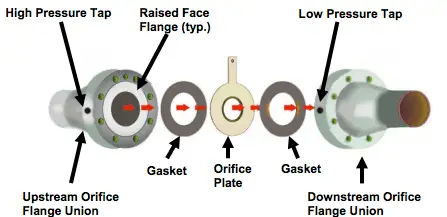
Orifice Plate Turndown ratio

The limitation of the DP-type flow meter using an orifice doesn’t come from the beta ratio limitation of the flow orifice plate nor any other flow orifice plate dimension.

The limitation comes from the error reading caused by the non-linear relationship between the differential pressure across the flow orifice plate and the calculated flow rate.

Orifice Plate Turndown Ratio

In simplified concept, we can calculate the orifice flow rate by:

Qm = C x (Differential Pressure)^0.5

Where,
Qm: Flow rate
C: Meter Constant
Differential Pressure: differential pressure across flow orifice plate

From the above equation, we know that the flow rate is proportional to the square root of the differential pressure. This non-linear relation produces a significant error in the lower flow when the turndown ratio exceeds 3:1.

Basically, the differential pressure transmitter itself can have a turndown ratio up to 100:1 but the square root extraction limits its capability in the upper range only.

See below calculation example below that illustrates the increase in error reading when the turndown ratio is below 3:1.

Example of Orifice Flow Meter Error Reading Calculation
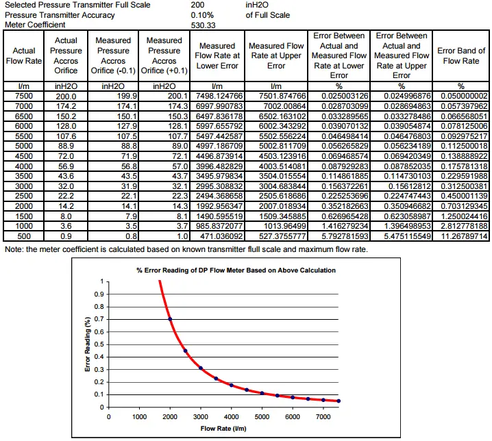
Orifice Flow Transmitter Turndown ratio

From the above example, we know that the % error reading (after performing the above square root calculation) is increasing along with the flow rate decreasing. The % error reading exceeds 0.5% when the flow rate is lower than 2500 l/m.

Let’s set this flow rate as our minimum flow rate since the flow rate measurement has having high error below this point. If we look further, the 2500 l/m minimum flow and 7500 l/m maximum flow correspond to the 3:1 turndown ratio. This is where the 3:1 turndown ratio is applied in our general practices.

If we insist on having minimum flow let’s say 1000 l/m then we will have a turndown ratio of 7.5:1. This will lead us to get an error reading of 2.8 % which means a very bad measurement accuracy.

Thus some engineer usually simply use a 3:1 turndown ratio as their rule of thumb to decide whether they will use a DP-type flow orifice plate flow meter or not.

If the required turn-down is higher than 3:1, then it will be better if we use another type of flow meter even though it is possible to have such a higher turn-down ratio by installing a parallel DP-type flow orifice plate flow meter with a split range configuration.

I don’t have any reason regarding this except the parallel configuration will give us a high cost of material procurement.

If you liked this article, then please subscribe to our YouTube Channel for Instrumentation, Electrical, PLC, and SCADA video tutorials.

You can also follow us on Facebook and Twitter to receive daily updates.

Read Next:

  • Flow Meter Turndown Ratio
  • Restriction orifice versus Orifice
  • Instrument Turndown Ratio
  • Flumes Flow Measurement
  • Rotameter Working Animation
Don't Miss Our Updates
Be the first to get exclusive content straight to your email.
We promise not to spam you. You can unsubscribe at any time.
Invalid email address
You've successfully subscribed !
What Factors Affect the Stability of Flow Meter Readings?
Thermal Dispersion Flow Switch Working Principle
Gas and Liquid Measurement: Processes and Solutions for the Industrial Sector
Bernoulli’s Principle and Equation – Flow Measurement
Coriolis Mass Flow Sensor Theory
Share This Article
Facebook Whatsapp Whatsapp LinkedIn Copy Link
Share
1 Comment
  • Andy says:
    January 23, 2017 at 4:09 pm

    Nice article, however if the full scale of the transmitter is 200 inH2O and the transmitter accuracy is 0.1% of full scale, is the error in pressure measure not +/- 0.2 inH2O rather than 0.1?

    Reply

Leave a Reply Cancel reply

Your email address will not be published. Required fields are marked *

Stay Connected

128.3kFollowersLike
69.1kFollowersFollow
208kSubscribersSubscribe
38kFollowersFollow

Categories

Recent Comments

  • Guifty Shimica on Top Non-PLC Certification Courses for Automation Professionals
  • Guifty Shimica on Top Non-PLC Certification Courses for Automation Professionals
  • MIHARITSOA Aina Sitraka on Top Non-PLC Certification Courses for Automation Professionals
  • Vaishnavi on Free Instrumentation Course for Trainee Engineers

Related Articles

Impulse line - Purpose & Tapping Point Location

Impulse Line – Purpose & Tapping Point Location

Flow Switch Principle

In-Line Flow Switch Working Principle and Animation

Flow Transmitter Output Current Calculation

Calculate Flow Transmitter Output Current

Insertion flow meters

What is an Insertion Flow Meter? – Types, Principle, Advantages

Flow meter Turndown Ratio

Why Turndown Ratio is important when Selecting a Flow Meter?

Square root extractor Parts

What is a Square Root Extractor? – DP Flow Measurement

mass flowmeters

What is a Thermal Flow Meter?

multi-hole-restriction-orifice-plate

Basics of Restriction Orifice (RO) – Types, Applications, Standards

More Articles

Electro deionization in a Water Treatment Plant

What is EDI in a Water Treatment Plant? – Electro deionization

FF Function block location

Foundation Fieldbus Logics

Types of PLC

#14 PLC Best Practices – Restrict Third-party Data Interfaces

Digital Electronics Objective Questions

Digital Electronics Objective Questions – Set 3

Closed Tank Application

Zero Elevation and Zero Suppression in Level Measurement

Digital Transducers Objective Questions

Digital Transducers Objective Questions

As-found and As-left Calibration

As-found and As-left Documentation during Calibration

Schneider PLC Programming Example

Schneider PLC Programming Example for Beginners

Follow US
All rights reserved. Reproduction in whole or in part without written permission is prohibited.
Welcome Back!

Sign in to your account

Username or Email Address
Password

Lost your password?