Inst ToolsInst ToolsInst Tools
  • Courses
  • Automation
    • PLC
    • Control System
    • Safety System
    • Communication
    • Fire & Gas System
  • Instrumentation
    • Design
    • Pressure
    • Temperature
    • Flow
    • Level
    • Vibration
    • Analyzer
    • Control Valve
    • Switch
    • Calibration
    • Erection & Commissioning
  • Interview
    • Instrumentation
    • Electrical
    • Electronics
    • Practical
  • Q&A
    • Instrumentation
    • Control System
    • Electrical
    • Electronics
    • Analog Electronics
    • Digital Electronics
    • Power Electronics
    • Microprocessor
  • Request
Search
  • Books
  • Software
  • Projects
  • Process
  • Tools
  • Basics
  • Formula
  • Power Plant
  • Root Cause Analysis
  • Electrical Basics
  • Animation
  • Standards
  • 4-20 mA Course
  • Siemens PLC Course
Reading: Why Orifice Flow Meter Flange is Not Recommended 150# Rating?
Share
Font ResizerAa
Inst ToolsInst Tools
Font ResizerAa
  • Courses
  • Design
  • PLC
  • Interview
  • Control System
Search
  • Courses
  • Automation
    • PLC
    • Control System
    • Safety System
    • Communication
    • Fire & Gas System
  • Instrumentation
    • Design
    • Pressure
    • Temperature
    • Flow
    • Level
    • Vibration
    • Analyzer
    • Control Valve
    • Switch
    • Calibration
    • Erection & Commissioning
  • Interview
    • Instrumentation
    • Electrical
    • Electronics
    • Practical
  • Q&A
    • Instrumentation
    • Control System
    • Electrical
    • Electronics
    • Analog Electronics
    • Digital Electronics
    • Power Electronics
    • Microprocessor
  • Request
Follow US
All rights reserved. Reproduction in whole or in part without written permission is prohibited.
Inst Tools > Blog > Flow Measurement > Why Orifice Flow Meter Flange is Not Recommended 150# Rating?

Why Orifice Flow Meter Flange is Not Recommended 150# Rating?

The Restriction Orifice can have a 150# flange rating but the Orifice Flow Meter Flange is not recommended to have a 150# flange.

Last updated: November 2, 2023 11:37 am
Editorial Staff
Flow Measurement Instrumentation Design
1 Comment
Share
2 Min Read
SHARE

This question comes to mind? As to Restriction Orifice can have 150# but the Orifice flange (Flow meter) is not recommended to have a 150# rating.

Contents
Orifice Flange Rating – 150#The PROOF
Orifice Flange Rating

Orifice Flange Rating – 150#

We have the answer in one sentence.

It is due to flange integrity !

It means in simple words :- Orifice that are flange tapped have reduced strength

Due to this drilling in between them their pressure-temperature retaining capacity reduces

So to ensure flanges have Strength to withstand Design pressure and temperature a higher rating than 150# i.e 300# is used .

Now There has to be some proof supporting It !!!

The PROOF

The standard we use for Normal flanges below 24” is ASME B16.5

But for Orifice, the flange standard is ASME B16.36

This standard starts with 300# Flange rating.

In restriction Orifice as there are no tapping hence we go with ASME B16.5 flanges which Start with 150# Rating .

As always ! Thanks a lot for Reading !!

PS :- It is observed that for very large line sizes ( Depends few say above 10”, few say above 20”) 150# can be used as these flanges are stronger at higher line sizes but I have not found concrete proof in standards yet.

I would be very grateful if somebody knows the standard that has this documented.

Author: Asad Shaikh

Profile: Linkedin

If you liked this article, then please subscribe to our YouTube Channel for Instrumentation, Electrical, PLC, and SCADA video tutorials.

You can also follow us on Facebook and Twitter to receive daily updates.

Read Next:

  • Orifice beta ratio values
  • ANSI Class Relates to PSI?
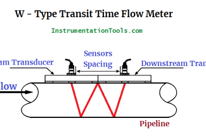
  • Characteristics of Flow Meter
  • Magnetic Meter Construction
  • K factor Formula of Flow Meter
Don't Miss Our Updates
Be the first to get exclusive content straight to your email.
We promise not to spam you. You can unsubscribe at any time.
Invalid email address
You've successfully subscribed !

Continue Reading

Instrument Air Compressor Control Philosophy
What is a Positive Displacement Flow Meter?
Oscillating Piston Flow Meters Working Principle
Detail Design Engineering Competency Aspects
Coriolis Flowmeter Advantages and Limitations
How to Select a Inductive Proximity Sensor
Share This Article
Facebook Whatsapp Whatsapp LinkedIn Copy Link
Share
1 Comment
  • Albert Hattingh says:
    December 16, 2023 at 3:12 pm

    which would be the best instrument to measure flow in a 4″ gas line? unfortunately the gas contains condensate.

    Reply

Leave a Reply Cancel reply

Your email address will not be published. Required fields are marked *

Stay Connected

128.3kFollowersLike
69.1kFollowersFollow
210kSubscribersSubscribe
38kFollowersFollow

Categories

Explore More

Temperature Gauges and Elements : Detailed Specifications
Orifice Plate Questions and Answers
Basics of Flow Measurement
Instrumentation Earthing
Explain Operation of the Lamp Circuit ?
Types of Flow Meters
Facts About Orifice Flow Meters
What is Contact bounce ?

Keep Learning

Basics of Thermistors, Thermocouples and RTD's

Basics of Thermistors, Thermocouples and RTD’s

Field Instruments Scaling and Unit Conversions

Field Instruments Scaling and Unit Conversions

Configure the Instruments in Flow Control Loop

Configure the Instruments in Flow Control Loop

Differential Pressure Flow Meters

Short Notes on Differential Pressure Flow Meters

Control System Vendor Internal Test Procedures

Vendor View of Supplying Industrial Process Control & Safety Systems

plc-analog-signals-wiring-techniques

PLC Analog Signals Wiring Techniques

Instrumentation Project Documents

List of Instrumentation Project Engineering Documents

Relay Permissive and interlock circuits

Basics of Permissive and Interlock Circuits

Learn More

FMCW Radar level transmitter Working Principle

FMCW Radar Level Transmitter Working Principle

Tube Fittings - 4

Tube and tube fittings

steadily pour a liquid into vertical tube

Vertical Tube Liquid Level Equilibrium

Pneumatic Load Cell Principle

Pneumatic Load Cell Principle

Troubleshooting Pump Control Circuit

Troubleshooting Pump Control Circuit

Typical process control loop

How Process Control Loop Works

HMI screen for operator

#8 PLC Best Practices – Validate HMI Input Variables at PLC Level

Transformers Interview Questions & Answers

Measurement and Instrumentation Objective Questions – Part 2

Menu

  • About
  • Privacy Policy
  • Copyright

Quick Links

  • Learn PLC
  • Helping Hand
  • Part Time Job

YouTube Subscribe

Follow US
All rights reserved. Reproduction in whole or in part without written permission is prohibited.
Welcome Back!

Sign in to your account

Username or Email Address
Password

Lost your password?