Inst ToolsInst ToolsInst Tools
  • Courses
  • Automation
    • PLC
    • Control System
    • Safety System
    • Communication
    • Fire & Gas System
  • Instrumentation
    • Design
    • Pressure
    • Temperature
    • Flow
    • Level
    • Vibration
    • Analyzer
    • Control Valve
    • Switch
    • Calibration
    • Erection & Commissioning
  • Interview
    • Instrumentation
    • Electrical
    • Electronics
    • Practical
  • Q&A
    • Instrumentation
    • Control System
    • Electrical
    • Electronics
    • Analog Electronics
    • Digital Electronics
    • Power Electronics
    • Microprocessor
  • Request
Search
  • Books
  • Software
  • Projects
  • Process
  • Tools
  • Basics
  • Formula
  • Power Plant
  • Root Cause Analysis
  • Electrical Basics
  • Animation
  • Standards
  • 4-20 mA Course
  • Siemens PLC Course
Reading: What is an Orifice Flange? – Purpose and Applications
Share
Font ResizerAa
Inst ToolsInst Tools
Font ResizerAa
  • Courses
  • Design
  • PLC
  • Interview
  • Control System
Search
  • Courses
  • Automation
    • PLC
    • Control System
    • Safety System
    • Communication
    • Fire & Gas System
  • Instrumentation
    • Design
    • Pressure
    • Temperature
    • Flow
    • Level
    • Vibration
    • Analyzer
    • Control Valve
    • Switch
    • Calibration
    • Erection & Commissioning
  • Interview
    • Instrumentation
    • Electrical
    • Electronics
    • Practical
  • Q&A
    • Instrumentation
    • Control System
    • Electrical
    • Electronics
    • Analog Electronics
    • Digital Electronics
    • Power Electronics
    • Microprocessor
  • Request
Follow US
All rights reserved. Reproduction in whole or in part without written permission is prohibited.
Inst Tools > Blog > Flow Measurement > What is an Orifice Flange? – Purpose and Applications

What is an Orifice Flange? – Purpose and Applications

An Orifice Flange is used in combination with orifice meters to measure flow rate of oil, gas and other liquids conveyed by the pipeline.

Last updated: November 2, 2023 11:38 am
Editorial Staff
Flow Measurement
No Comments
Share
3 Min Read
SHARE

An Orifice Flange is used in combination with orifice meters to measure the flow rate of oil, gas, and other liquids conveyed by the pipeline.

Contents
Orifice FlangePurpose of an Orifice FlangeApplications of Orifice Flange

Orifice flanges are manufactured to ASME B16.36 in multiple sizes and, material grades.
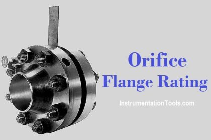
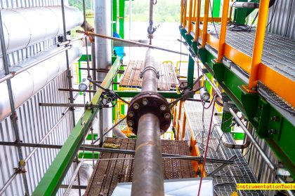
Orifice Flange

An orifice flange is used to measure the flow of the fluid conveyed by the pipeline via a flow nozzle positioned on the flange itself. Pairs of pressure tappings are machined onto the orifice flange, making separate tappings on the pipe wall unnecessary.

An Orifice flange is a disc-shaped flange, engineered with either a Raised Face or a Ring Type of Joint facing.

What is an Orifice Flange ?

The traditional orifice flange assembly consists of a pair of flanges, orifice plates, bolts, nuts, gaskets, jacking screws, and plugs. Jacking screws ensure the easy removal of the primary flow element.

Orifice flanges are available in all ASTM forged grades (ASTM A105, ASTM A350, ASTM A694, ASTM 182 respectively for carbon, alloy and, stainless steel flanges), dimensions (combinations of nominal sizes and pressure ratings) and, in socket weld, threaded or weld neck shape (WN is the most used).

Purpose of an Orifice Flange

1. They are widely used with orifice meters to measure the flow rate of either liquid or gases, flowing through the pipe.

2. An orifice plate, a device measuring the flow of the inner fluid or gas, is secured between two orifice flanges, attached to the pipe.

3. The orifice plate contains a small hole; two pressure tap holes are drilled in each flange which helps in measuring the pressure built inside the pipe.

4. A ‘jack screw’ fitted between the two flanges, it enables to separate the flanges during inspection or replacement process.

Applications of Orifice Flange

These flanges are used in the following industries:

  • Heavy and light chemicals
  • Steel
  • Paper
  • Nuclear
  • Petrochemicals
  • Sewage treatment
  • Water treatment and distribution
  • Power Generation
  • Oil production and refining
  • Gas Processing and transmission

Reference :

  • ugsteelmill
  • bhansalioverseas

If you liked this article, then please subscribe to our YouTube Channel for Instrumentation, Electrical, PLC, and SCADA video tutorials.

You can also follow us on Facebook and Twitter to receive daily updates.

Read Next:

  • Flow Nozzle Principle
  • Types of Flow Sensors
  • Flow Meter Totalizer
  • Turbine Meter Factor
  • Flow Standards
Don't Miss Our Updates
Be the first to get exclusive content straight to your email.
We promise not to spam you. You can unsubscribe at any time.
Invalid email address
You've successfully subscribed !

Continue Reading

Pitot Tube Working Principle
Orifice Plate Tapping – Orifice Plate Taps
Open Channel Flow Measurement Principle
Magnetic Flowmeter vs. Turbine Flowmeter – Comparison
Rotary Abutment Flow Meters Working Principle and Animation
What is a Coriolis Flow Meter?
Share This Article
Facebook Whatsapp Whatsapp LinkedIn Copy Link
Share
Leave a Comment

Leave a Reply Cancel reply

Your email address will not be published. Required fields are marked *

Stay Connected

128.3kFollowersLike
69.1kFollowersFollow
210kSubscribersSubscribe
38kFollowersFollow

Categories

Explore More

Ultrasonic Flow Meters Working Principle
Electromagnetic Flow Meters Working Principle
What is Differential Pressure Flow Meter?
Importance of Flow Meter Turndown Ratio
Oscillating Piston Flow Meters Working Principle
Difference between Fixed Area & Variable Area FlowMeters
Calculate Flow Transmitter Output Current
Why Flow is Directly Proportional to the Square Root of DP?

Keep Learning

Averaging Pitot Tube Principle

What is a Torbar? – Averaging Pitot Tubes

Differential Pressure (DP) Flow Meters Range Calculation Methods

Differential Pressure (DP) Flow Meters Range Calculation Methods

Types of Flow Meters

Types of Flow Meters

Orifice Specifications

Orifice Flow Meters: Detailed Specifications

Flow Meters Troubleshooting

Turbine Flow Meters Troubleshooting

Orifice Beta

Why is Orifice Beta in between 0.3 to 0.7?

Ultrasonic Doppler Flow Meter Advantages and Disadvantages

Ultrasonic Doppler Flow Meter Advantages and Disadvantages

What is a Condensate Pot? How to Install it?

Learn More

Power Electronics Objective Questions

Choppers Test Questions

Power Electronics Objective Questions

Thyristor Rating Objective Questions and Answers

What is Process Control ?

What is Process Control?

Turbine Bypass System

Turbine Bypass System

Open Diode in a Full-Wave Rectifier

Power Supply Circuit Fault Analysis

Valve Positioner Torn apart

Pipeline Shakes Torn apart Valve Positioners

Single-acting Pneumatic Cylinder operation with Limit Switch

Single-acting Pneumatic Cylinder Operation with Limit Switch

Time Response Analysis

Performance Indices

Menu

  • About
  • Privacy Policy
  • Copyright

Quick Links

  • Learn PLC
  • Helping Hand
  • Part Time Job

YouTube Subscribe

Follow US
All rights reserved. Reproduction in whole or in part without written permission is prohibited.
Welcome Back!

Sign in to your account

Username or Email Address
Password

Lost your password?