In a previous article, we discussed what an organization block is, and we talked about one very important organization block, which is the main OB1.
In this article, we will continue discussing the different OBs and this time we are talking about the time of day interrupt organization blocks or OB10.
Contents:
- What is time of day Interrupt OB10?
- How to create and use OB10?
- Simple program example.
- Important Rules for the time of day interrupts.
- Conclusions.
What is a Time of Day Interrupt (OB10)?
As the name suggests, a time of day interrupt is an organization block that will interrupt the execution of the main cycle of your PLC program at a certain time of the day. This interrupt time (date and time) can be specified to occur once at a specified time or to occur periodically at specified time intervals, for example, every minute, hour, day, week, and some other options.
You can have more than one time-of-day interrupt in the same program, they don’t have to have the same logic or code, each one can have its own functionality and also each one can be configured separately to occur at a specified time.
How to Create and Use OB10?
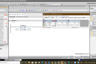
To create a time of day interrupt you follow the same steps you would do if you need to add any new block into your logic. See picture 1.
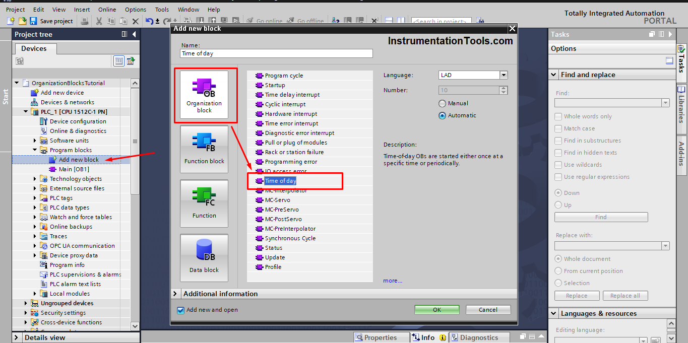
Press the Add new block option in the project tree on the left, choose organization block, and then choose a time of day interrupt as shown in the previous picture.
Now you can open the OB10 and add whatever PLC logic you want to execute when this block is called, by called we mean that the interrupt event or time has occurred and so the operating system will interrupt the main cycle and execute the OB10.
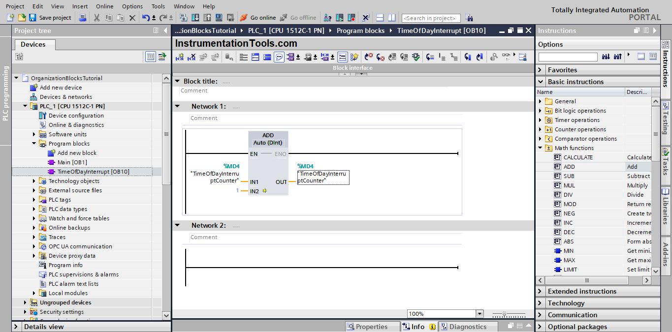
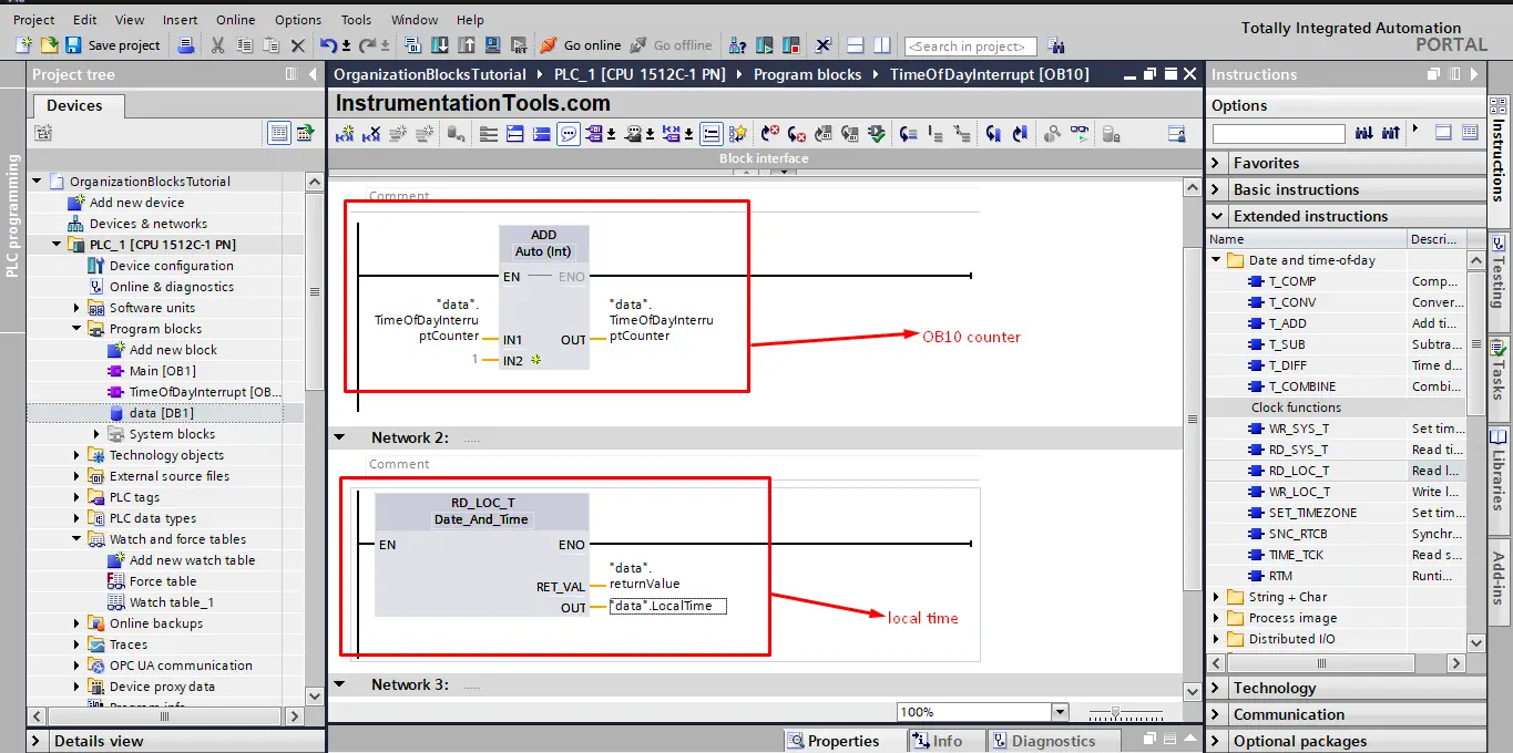
We will write a very simple code into the OB10 to help us better understand how this OB10 block works. In this logic, we used add instruction to add a value of 1 to a memory area that we called TimeOfDayInterruptCounter and then put the result of the summation back in the same area. That way we can have a counter for the execution of the OB10.
Each time the OB10 will be called and executed, the value of TimeOfDayInterruptCounter will increase by 1. See picture 2.
Now that we have created the OB10 and written some logic inside, we need to configure the set time of the OB10 and how many times we want it to interrupt our main cycle.
To configure the time and interval setting of the OB10 we need to go to the properties page of the OB10. See picture 3.
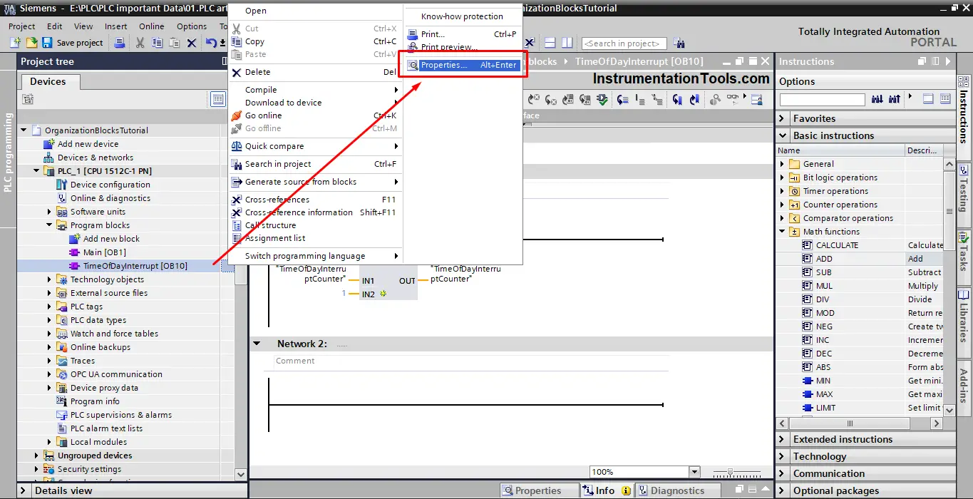
In the properties of the OB10, you will find a lot of settings and attributes that you can configure.
What we need now is the time of day interrupt page so we can set up when the OB10 will be called and how many times. See picture 4.
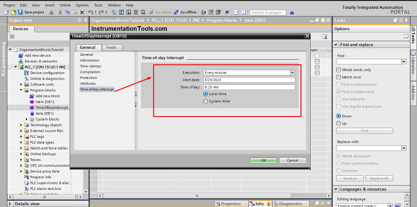
As you see from the last picture, you can set the execution of OB10, the start date, and the time of day at which the OB10 should be executed.
For the sake of simulation, we made the execution interval to be every minute so that every minute the OB10 will be called and executed. That means starting from the date of 3/23/2023 and time 09:25 AM the value of TimeOfDayInterruptCounter will increase by 1 every minute.
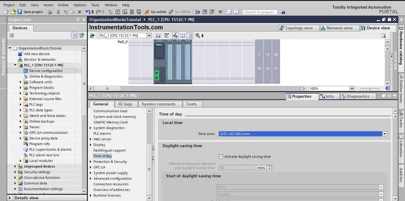
You have the option of setting the time according to the PLC system time or local time as you see from the last picture. In a previous article, we talked about the system and local time of the PLC, what each time mean, and how to configure and use them.
As we said before the local time is the time you see now on your PC. So it is the actual time of the region where the PLC will be used.
You have to configure the local time for the PLC, depending on where it will be used. See picture 5.
Simple PLC Program Example
We added a time of day interrupt OB10 to our PLC program and we have set it so it will be executed every minute. We also have configured the local time of the PLC.
We created a simple logic of an ADD instruction to accumulate the value of the TimeOfDayInterruptCounter by 1 each time the OB10 is executed.
We will add another instruction, but in the main OB1, this instruction is RD_LOC_T or read local time, so we can see how the local time is progressing and compare it with the execution of OB10. See picture 6.
Compile your PLC program and start a new simulation.
Notice that we will set the time of day interrupt occurrence so that the OB10 can be called and executed while we are simulation the PLC logic. See the following simulation.
As you see from the animation, the value of TimeOfDayInterruptCounter is zero at the start and then it will be increased by 1 every minute starting from time 09:25 AM indicating that the OB10 is being executed every minute.
Important Rules for the Time of Day Interrupts
- If you set a time interrupt in such a way that the corresponding OB is to be processed once, the start time must not be in the past (relative to the real-time clock of the CPU).
- If you set a time interrupt in such a way that the corresponding OB is to be processed periodically, but the start time is in the past, then the time interrupt OB is processed the next time it is due according to the current time.
- The date of periodic time interrupts must correspond to a real date. For example, the monthly repetition of a time interrupt OB with a start date of 1/31 is therefore not possible. In this case, an OB is only started in the months that have 31 days.
- A time interrupt activated during startup is not executed until the startup has been completed.
- A startup deletes all time interrupts that were set and activated by an instruction in the user program.
Downloads:
Conclusion
OB10 is an organization block that can be configured to interrupt the cycle of your program at a certain day and time. This interrupt can either occur once or periodically every certain amount of time.
No specific reason why would you need an OB10, as it depends on your process and your logic. And yes, you can achieve the same functionality using your personal code, but it is an available and easy-to-use built-in function. And you know how to use it.
If you liked this article, then please subscribe to our YouTube Channel for Instrumentation, Electrical, PLC, and SCADA video tutorials.
You can also follow us on Facebook and Twitter to receive daily updates.
Read Next:
- Global Data Blocks in PLC
- Timers in Siemens Tia Portal
- SCADA System Architecture
- Static and Temp Variables in PLC
- PLC Programming Best Practices